Chapter 9 Electrical
System
.;;.5
....
A_lt_er_n_a_to_r...;(_O_P_T_l_O_N_A_L_)
_____________________
3,4JH3(B)(C)E
(6}
IC
regulator"
Connect the variable resistance, two 12V batteries,
resistor, and voltmeter as shown
in
the diagram.
1) Use the following measuring devices.
Resistor
(R1)
1000,
2W, 1pc.
Variable resistor (Rv)
0-3000,
12W, 1pc.
Battery (BAT1,
BAT2)
12V. 2pcs
DC voltmeter
0-30V,
0.5 class 1 pc.
(measure at 3 points)
2) Check the regulator in the following sequence, accor-
ding to the diagram.
a}
Check
V3,
(BAT,+BAT2
voltage).
If
the voltage is
20-26V, both
BAT1,
and
BAT2,
are normal.
b)
While measuring
V2
(F-E terminal voltage). move
Rv gradually from the O-position. Check
if
there
is a point where the
V2,
voltage rises sharply from
below 2.0V to over 2.0V.
If
there is no such point,
the regulator is defective. Replace the regulator
If
there
is
a sharp voltabe rise when testing, return the
Av to the 0-position, and connect the voltmeter to
the
V1,
position.
c) While measuring
V1
(voltage between L-E termi nals),
move
RV
gradually
from the
O-position.
There
should
be
a point where the voltage of V,, rises
sharply by 2-6V. Measure the voltabe ol
V1,
just
before this sharp voltage rise. This is the regulating
voltage of the regulator.
If
this voltage of
V,,
is within
the standard limit, the regulator is normal.
If
the
voltage deviates from the limit, the regulator is
defective.
Replace the regulator.
l..__E
----'-F------'L=--___:_:_R _
__:_:_R
_j
5-9 Reassembling the alternator
Reassembly is done in the reverse order of disassembly.
For reassembly, be careful of the following points (Refer
to
4-7 disassembling alternator.)
(1) Assembling the brush regulator
1}
Solder the brush.
Position the brush as shown
in
the drawing and solder
it.
Be
careful not to let the solder drip into the pig tail
(lead wire).
9-36
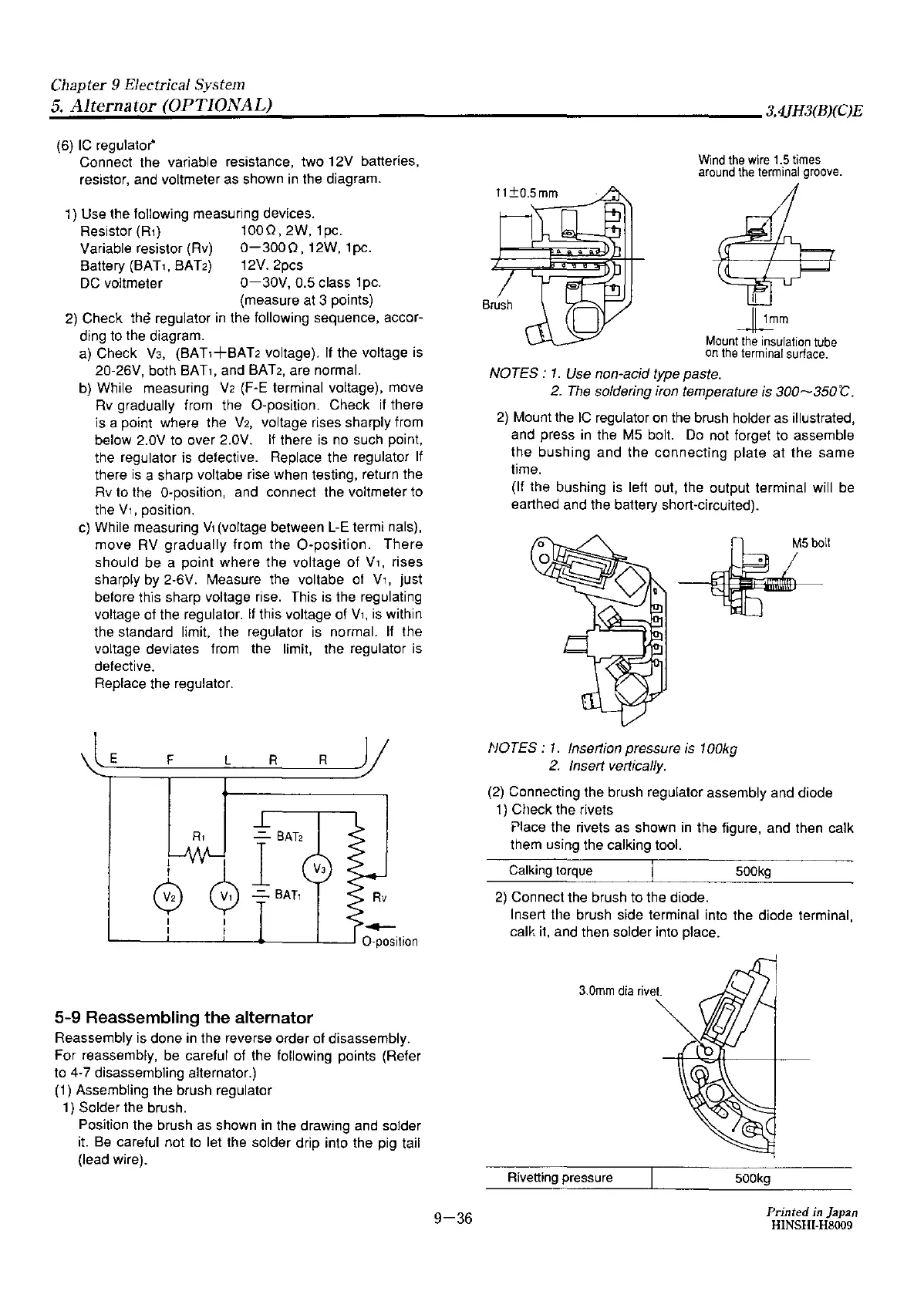
Wind
the
wire
1.5
times
around
the
terminal
groove.
II
~mm
Mount
the
insulation
tube
on
1he
terminal
surface.
NOTES:
1.
Use non-acid type paste.
2.
The
soldering iron temperature is 300~350"C.
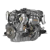
2)
Mount the
IC
regulator on the brush holder
as
illustrated,
and press in the M5 bolt.
Do
not forget to assemble
the bushing and the connecting plate at the
same
time.
(If the bushing is left out, the output terminal will be
earthed and the battery short-circuited).
M5boll
NO
TES
:
1.
Insertion pressure
is
100kg
2.
Insert vertically.
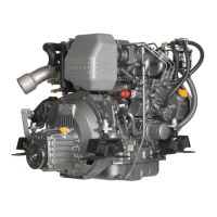
(2)
Connecting the brush regulator assembly and diode
1)
Check the rivets
Place the rivets as shown
in
the figure, and then calk
them using the calking tool.
Calking
torque
500kg
2)
Connect the brush to the diode.
Insert the brush side terminal into the diode terminal,
calk it, and then solder into place.
3.0mm
dia
rivet.
Rivetting pressure
500kg
Printed
in
Japan
HINSHI-H8009