Chapter 3 Fuel Injection Equipment
_4._A_d.;;..Ju_s_t_m_e_n_t_o_f_F_u_e_l_l_n_Je_c_t_io_n_P_u_m
...
p_an_d_G_o_v_e_r_n_or
______________
3,4JH3(B)(C)E
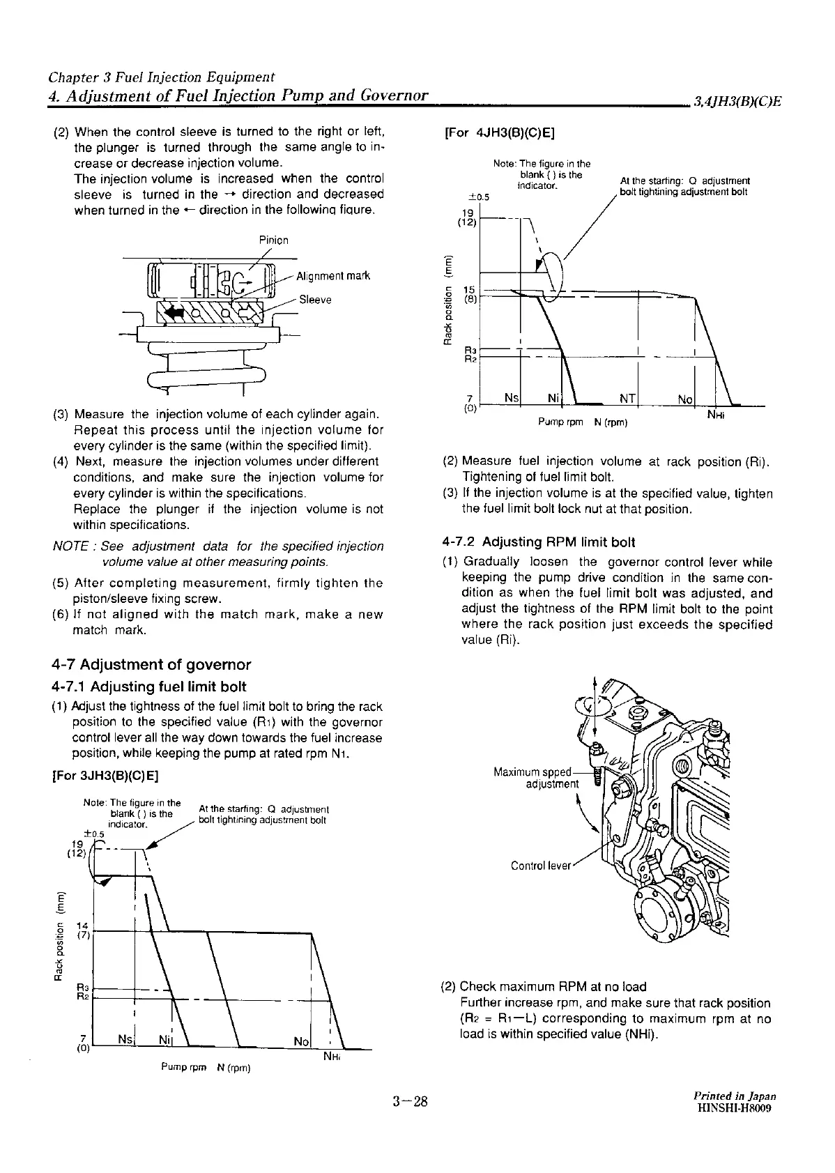
(2)
When the control sleeve
is
turned to the right or left,
the plunger
is
turned through the same angle to in-
crease or decrease injection volume.
The injection volume is increased when the control
sleeve
is
turned
in
the
-.
direction and decreased
when turned
in
the+-
direction
in
the followinq fioure.
Pinion
Alignment
mark
Sleeve
(3) Measure the injection volume of each cylinder again.
Repeat this process until the injection volume for
every cylinder
is
the same (within the specified limit).
(4) Next, measure the injection volumes under different
conditions, and make sure the injection volume for
every cylinder
is
within the specifications.
Replace the plunger if the injection volume
is
not
within specifications.
NOTE:
See adjustment data for
the
specified injection
volume value at other measuring points.
(5)
After
completing
measurement, firmly tighten the
piston/sleeve fixing screw.
(6) If not
aligned
with the match mark,
make
a
new
match mark.
4-7 Adjustment
of
governor
4-7.1 Adjusting fuel limit
bolt
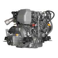
(1)
Mjust
the
tightness of the fuel limit bolt to bring
the
rack
position to the specified value
(R1)
with the governor
control lever
all
the way down towards
the
fuel increase
position, while keeping the pump at rated
rpm
N1.
[For 3JH3(B)(C)E]
E
.s
C
.g
·;;;
g_
-"'
0
fO
a:
Note: The figure
in
the , .
blank ( )
is
the
At
!he star/mg: Q adIustment
19
indicator/
bolt
t1gh1m1ng
ad1ustment bolt
±0,5
(12)
-
----n
14
(7)
R3
R2
Pump rpm N (rpm)
3-28
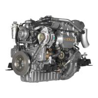
[For 4JH3(B)(C)E]
E
E
C
0
.:;
·;;;
0
a.
-"'
0
fO
er.
±0.5
19
(12)
15
(8)
RJ
R2
Note: The figure
in
the
blank ( )
IS !he
mdicator
At
the starling· Q adJustment
--
\
· / bolt tighllning adjustment bolt
Pump rpm
N (rpm)
(2) Measure fuel injection volume at rack position (Ri).
Tightening of fuel limit bolt.
(3)
If
the injection volume
is
at
the specified value, tighten
the fuel limit bolt lock nut
at
that position.
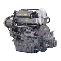
4-7.2 Adjusting RPM limit bolt
(1) Gradually loosen the governor control lever while
keeping the pump drive condition
in
the same con-
dition
as
when the fuel limit bolt was adjusted, and
adjust the tightness of
the
RPM limit bolt to the point
where the rack position just exceeds the specified
value (Ri).
Maximum
spped
adjuslme
Control
lever
(2)
Check maximum RPM at no load
Further increase rpm, and make sure that rack position
(R2
=
R1-L}
corresponding to maximum rpm at no
load
is
within specified value (NHi).
Printed in Japan
HINSHI-H8009