Chapter 3 Fuel Injection Equipment
~4~.A~d~iu~s~t=m~e~.n~t~o~f~F~u~e~l~In~1.e~ct~fu~n~P.u_m~p;....;.a~nd_._G_o_v_e_rn_o_r
______________
~4JH~BXC)E
4-
7 .3
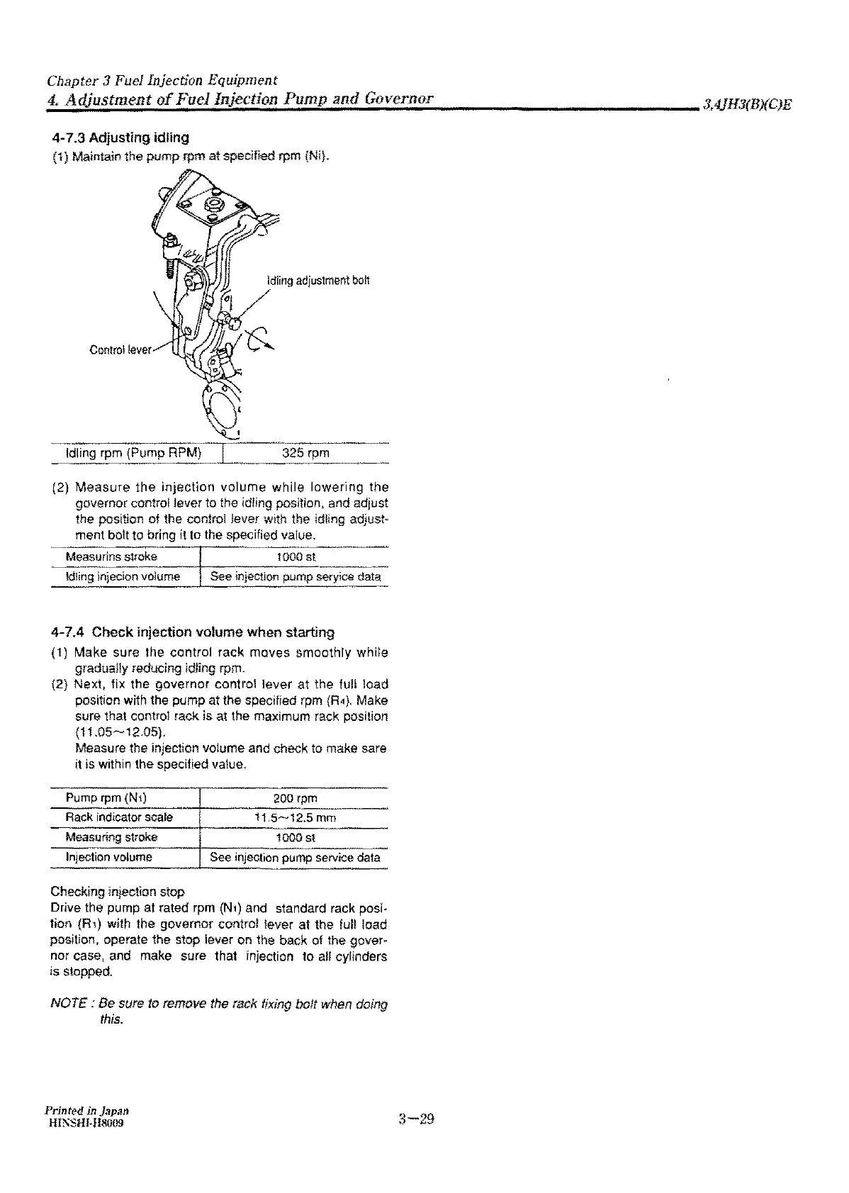
Adjusting
idling
{1} Maintain the
pump
rpm
at
speclfled rpm {Ni}.
Control
!-ever
Idling rpm {Pump RPM} 325 rpm
(2) Measure the
injection
volume
while
lowering
the
governor control lever to the idling position, and adjust
the position
of
the con!rol lever with the idling adjust-
ment bolt to bring
it
to
the specified value.
Measurins
~roke
1000
st
Idling injecion volume See injection pump seryice data
4-7.4 Check injection volume when starting
( 1) Make sure the control
rack
moves
smoothly
white
gradually reducing idling rpm.
(2} Next, fix the
governor
control
lever
at
the full load
position with the pump at the specified rpm
{R4},
Make
sure that control rack
is
a1
the maximum rack position
(11.05~12.05}.
Measure the injection volume and check to make sare
it
is within the specified value.
Pump rpm (N1)
200 rpm
Rack
indicator scale
115~12.5
mm
Measuring stroke
1000
st
Injection volume
See injection
pump
seNice
data
Checking injection stop
Drive the pump at rated rpm
(N1)
and standard rack posi•
fion
(R1) with the governor control lever at the full load
position, operate the stop lever on the back of the gover•
nor case, and make sure that injection
to
afl cylinders
is
stopped.
NOTE:
Be sure
to
remove the rack fixing bolt when doing
this.
Printed in
Japan
HI.1\SHJ.ll8009
3-29