The power supply was switched off within 5
seconds after changing the frequency
reference when o2-05 is set to 1.
Set up the external operation to allow at least 5 seconds pass before the power supply is shut off and after
changing the frequency reference while o2-05 is set to 1.
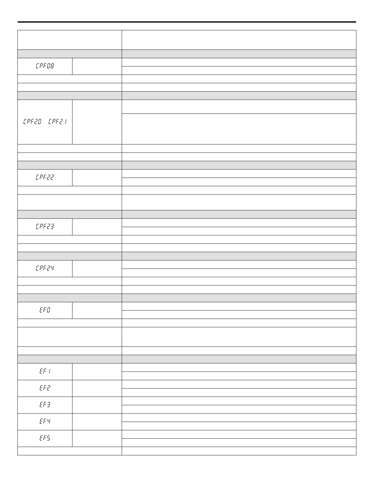
LED Operator Display Fault Name
CPF08
EEPROM Communication Fault
EEPROM communications are not functioning properly.
Cause Possible Solution
Control circuit is damaged. Cycle power to the drive. If the problem persists, replace the drive.
LED Operator Display Fault Name
or
CPF20 or CPF21
One of the following faults occurred: RAM fault, FLASH memory error, watchdog circuit exception,
clock error
• RAM fault.
•
FLASH memory error (ROM error).
• Watchdog circuit exception (self-diagnostic error).
• Clock error.
Cause Possible Solution
Hardware is damaged. Replace the drive.
LED Operator Display Fault Name
CPF22
A/D Conversion Fault
A/D conversion error.
Cause Possible Solution
Control circuit is damaged.
• Cycle power to the drive. Refer to Diagnosing and Resetting Faults on page 146.
•
If the problem continues, replace the drive.
LED Operator Display Fault Name
CPF23
PWM Feedback Fault
PWM feedback error.
Cause Possible Solution
Hardware is damaged. Replace the drive.
LED Operator Display Fault Name
CPF24
Drive Capacity Signal Fault
Entered a capacity that does not exist. (Checked when the drive is powered up.)
Cause Possible Solution
Hardware is damaged. Replace the drive.
LED Operator Display Fault Name
EF0
MEMOBUS/Modbus Communication External Fault
An external fault condition is present.
Cause Possible Solution
An external fault was received from the PLC
with other than H5-04 = 3 “alarm only” (the
drive continued to run after external fault).
• Remove the cause of the external fault.
•
Remove the external fault input from the PLC.
Problem with the PLC program. Check the PLC program and correct problems.
LED Operator Display Fault Name
EF1
External Fault (input terminal S1)
External fault at multi-function input terminal S1.
EF2
External Fault (input terminal S2)
External fault at multi-function input terminal S2.
EF3
External Fault (input terminal S3)
External fault at multi-function input terminal S3.
EF4
External Fault (input terminal S4)
External fault at multi-function input terminal S4.
EF5
External Fault (input terminal S5)
External fault at multi-function input terminal S5.
Cause Possible Solution
6.4 Fault Detection
134
YASKAWA ELECTRIC SIEP C710606 31B YASKAWA AC Drive – J1000 Technical Manual
http://nicontrols.com
 Loading...


