An external device has tripped an alarm
function.
Remove the cause of the external fault and reset the fault.
Wiring is incorrect.
• Ensure the signal lines have been connected properly to the terminals assigned for external fault
detection (H1-oo = 20 to 2F).
•
Reconnect the signal line.
Incorrect setting of multi-function contact
inputs.
•
Check if the unused terminals set for H1-oo = 20 to 2F (External Fault).
•
Change the terminal settings.
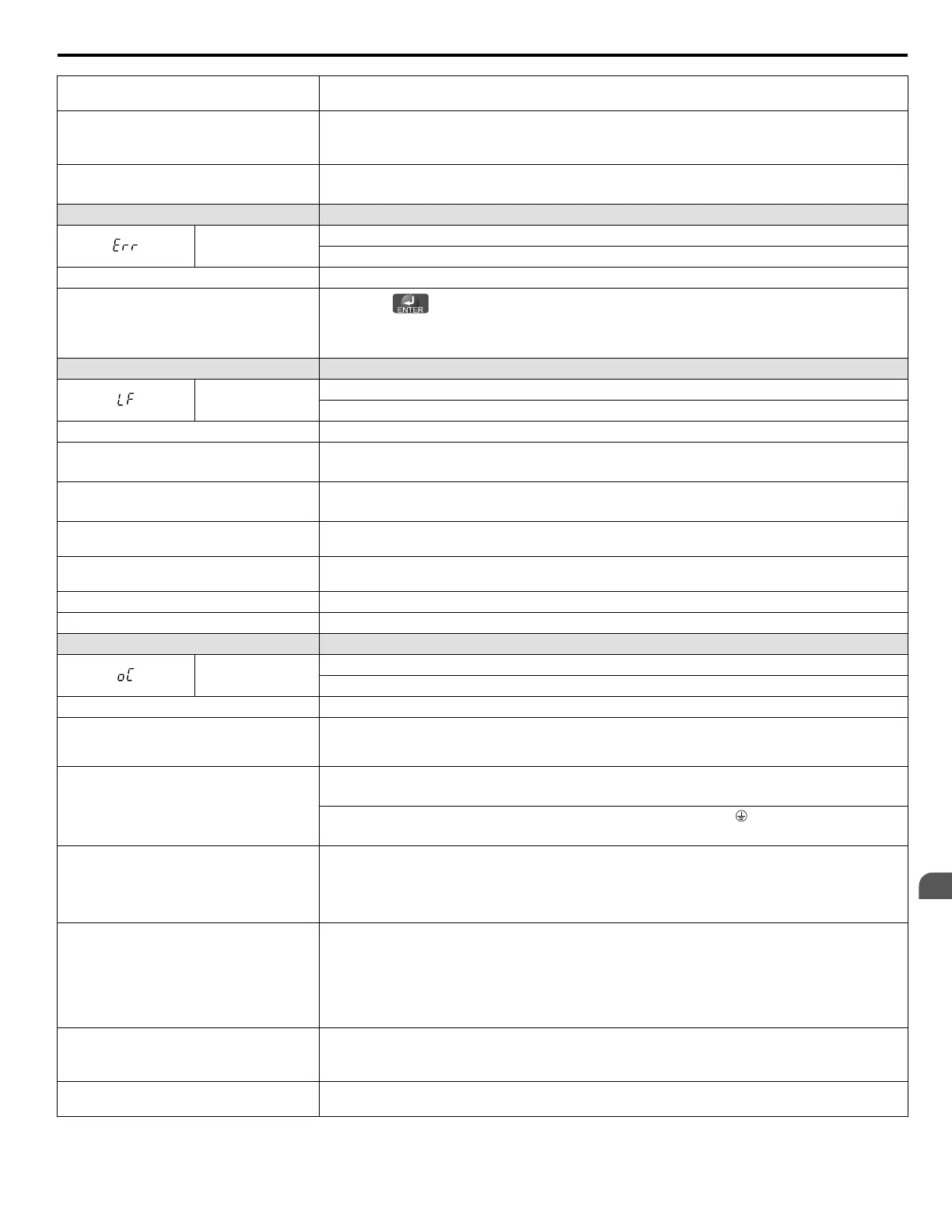
LED Operator Display Fault Name
Err
EEPROM Write Error
Data does not match the EEPROM being written to.
Cause Possible Solution
-
•
Press the
button.
•
Correct the parameter settings.
• Cycle power to the drive. Refer to Diagnosing and Resetting Faults on page 146.
LED Operator Display Fault Name
LF
Output Phase Loss
Phase loss on the output side of the drive.
Cause Possible Solution
The output cable is disconnected.
• Check for wiring errors and ensure the output cable is connected properly.
•
Correct the wiring.
The motor winding is damaged.
• Check the resistance between motor lines.
• Replace the motor if the winding is damaged.
The output terminal is loose.
• Apply the tightening torque specified in this manual to fasten the terminals. Refer to Wire Size and
Torque Specifications on page 44.
The motor being used is less than 5% of the
drive rated current.
Check the drive and motor capacities.
An output transistor is damaged. Replace the drive.
A single-phase motor is being used. The drive being used cannot operate a single phase motor.
LED Operator Display Fault Name
oC
Overcurrent
Drive sensors have detected an output current greater than the specified overcurrent level.
Cause Possible Solution
The motor has been damaged due to
overheating or the motor insulation is
damaged.
• Check the insulation resistance.
•
Replace the motor.
One of the motor cables has shorted out or
there is a grounding problem.
• Check the motor cables.
• Remove the short circuit and power the drive back up.
• Check the resistance between the motor cables and the ground terminal
.
•
Replace damaged cables.
The load is too heavy.
• Measure the current flowing into the motor.
• Replace the drive with a larger capacity unit if the current value exceeds the rated current of the drive.
• Determine if there is sudden fluctuation in the current level.
• Reduce the load to avoid sudden changes in the current level or switch to a larger drive.
The acceleration or deceleration times are too
short.
Calculate the torque needed during acceleration relative to the load inertia and the specified acceleration
time.
If the right amount of torque cannot be set, make the following changes:
• Increase the acceleration time (C1-01, -03)
• Increase the S-curve characteristics (C2-01 through C2-04)
• Increase the capacity of the drive.
The drive is attempting to operate a specialized
motor or a motor larger than the maximum size
allowed.
• Check the motor capacity.
• Ensure that the rated capacity of the drive is greater than or equal to the capacity rating found on the
motor nameplate.
Magnetic contactor (MC) on the output side of
the drive has turned on or off.
Set up the operation sequence so that the MC is not tripped while the drive is outputting current.
6.4 Fault Detection
YASKAWA ELECTRIC SIEP C710606 31B YASKAWA AC Drive – J1000 Technical Manual
135
6
Troubleshooting
http://nicontrols.com

 Loading...


