Cause Possible Solutions
Minor Fault
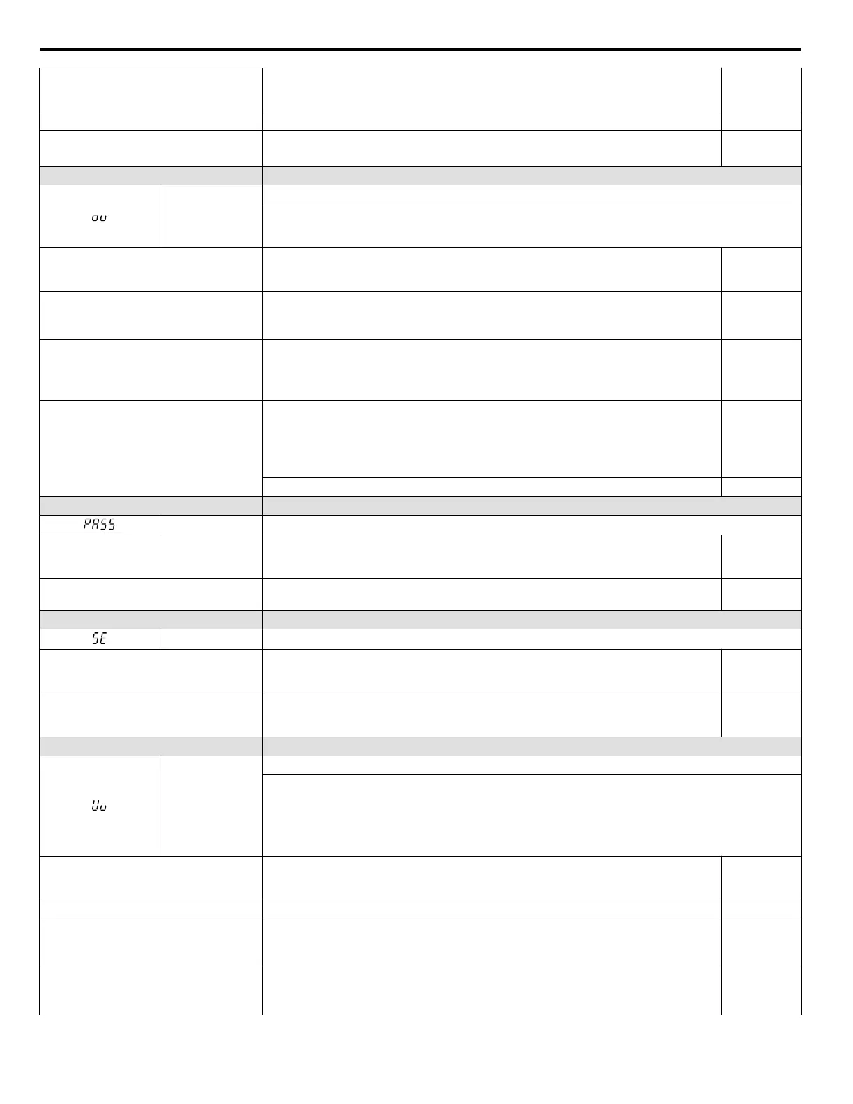
Output
(H2-01 = 10)
Inappropriate parameter settings. Check parameters L6-02 and L6-03. YES
There is a fault on the machine side (e.g., the
machine is locked up).
• Check the status of the machine.
•
Remove the cause of the fault.
YES
LED Operator Display Minor Fault Name
ov
DC Bus Overvoltage
The DC bus voltage exceeded the trip point.
For 200 V class: approximately 410 V
For 400 V class: approximately 820 V (740 V when E1-01 < 400)
Cause Possible Solutions
Minor Fault
Output
(H2-01 = 10)
Surge voltage present in the drive input
power.
• Install a DC link choke or an AC reactor.
•
Voltage surge can result from a thyristor convertor and a phase advancing capacitor
operating on the same drive input power system.
YES
• The motor is short-circuited.
• Ground current has over-charged the
main circuit capacitors via the drive input
power.
• Check the motor power cable, relay terminals and motor terminal box for short circuits.
• Correct grounding shorts and turn the power back on.
YES
Noise interference causes the drive to
operate incorrectly.
• Review possible solutions for handling noise interference.
• Review section on handling noise interference and check control circuit lines, main circuit
lines and ground wiring.
• If the magnetic contactor is identified as a source of noise, install a surge protector to the
MC coil.
YES
Set number of fault restarts (L5-01) to a value other than 0. YES
LED Operator Display Minor Fault Name
PASS MEMOBUS/Modbus Communication Test Mode Complete
Cause Possible Solutions
Minor Fault
Output
(H2-01 = 10)
MEMOBUS/Modbus test has finished
normally.
This verifies that the test was successful. No output
LED Operator Display Minor Fault Name
SE MEMOBUS/Modbus Communication Test Mode Error
Cause Possible Solutions
Minor Fault
Output
(H2-01 = 10)
A digital input programmed to 67H
(MEMOBUS/Modbus test) was closed
while the drive was running.
Stop the drive and run the test again. No output
LED Operator Display Minor Fault Name
Uv
Undervoltage
One of the following conditions occurred while the drive was in operation:
• DC bus voltage dropped below the under voltage detection level.
• Contactor to suppress inrush current in the drive was open.
• Low voltage in the control drive input power. This alarm outputs only if L2-01 is not 0 and DC bus voltage
is below the detection level.
Cause Possible Solutions
Minor Fault
Output
(H2-01 = 10)
Phase loss in the drive input power. Check for wiring errors in the main circuit drive input power. Correct the wiring. YES
Loose wiring in the drive input power
terminals.
• Ensure the terminals have been properly tightened.
• Apply the tightening torque specified in this manual to fasten the terminals. Refer to
Wire Gauges and Tightening Torque on page 39
YES
There is a problem with the drive input
power voltage.
• Check the voltage.
• Lower the voltage of the drive input power so that it is within the limits listed in the
specifications.
YES
6.5 Alarm Detection
142
YASKAWA ELECTRIC SIEP C710606 31B YASKAWA AC Drive – J1000 Technical Manual
http://nicontrols.com
 Loading...


