Cause Possible Solutions
Multi-function analog input is
set up to accept gain for the
frequency reference, but no
voltage (current) has been
provided.
• Check the multi-function analog input settings.
•
Check if H3-02 has been set to the proper values.
• Check if the analog input value has been set properly.
The
STOP
button was pressed
when the drive was started from
a REMOTE source.
•
When the
STOP
button is pressed, the drive will decelerate to stop.
•
Switch off the run command and then re-enter a run command.
•
The
STOP
button is disabled when o2-02 is set to 0.
Motor is not producing enough
torque.
• Ensure the selected V/f pattern corresponds with the characteristics of the motor being used.
• Increase both the minimum and mid output frequency voltages (E1-08, E1-10).
Increase the frequency reference so that it is higher than the minimum frequency reference (E1-09).
Increase the torque compensation gain (C4-01).
The drive is set for both 2-Wire
and
3-Wire sequence at the same
time.
• The drive is set for a 3-Wire sequence when one of the parameters H1-03 through H1-05 is set to 0.
• If
the drive is supposed to be set up for a 2-Wire sequence, then ensure parameters H1-03 through H1-05 are not set
to 0.
•
If the drive is supposed to be set up for a 3-Wire sequence, then H1-oo must be set to 0.
n
Motor Rotates in the Opposite Direction from the Run Command
Cause Possible Solutions
Phase wiring between the drive and motor is incorrect.
• Check the motor wiring.
•
Switch two motor cables (U, V, and W) to reverse motor direction.
• Connect drive output terminals U/T1, V/T2 and W/T3 in the right order to the corresponding
motor terminals U, V, and W.
• Change the setting of parameter b1-14.
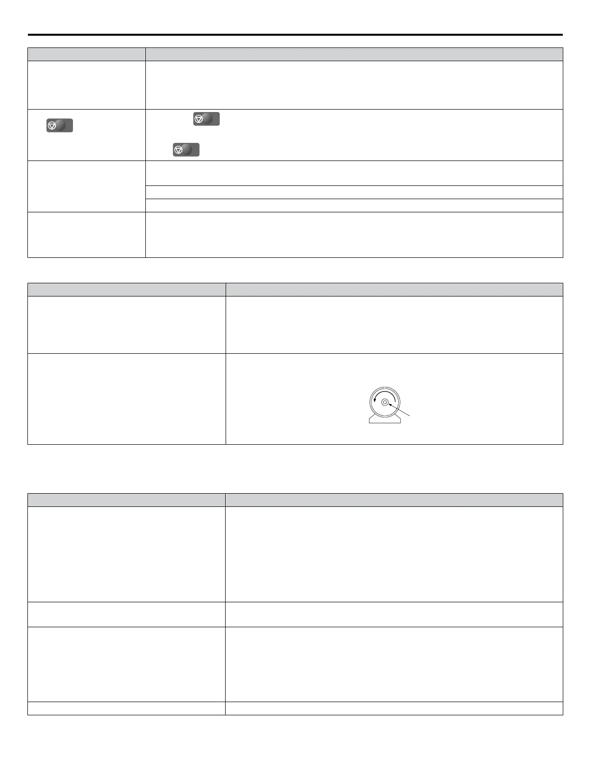
The forward direction for the motor is setup incorrectly.
Typically, forward is designated as being counterclockwise when looking from the motor shaft
(refer to the figure below).
1
2
1. Forward Rotating Motor (looking down the motor shaft)
2. Motor Shaft
Note: Check the motor specifications for the forward and reverse directions. The motor specifications will vary depending on the manufacturer
of the motor.
n
Motor is Too Hot
Cause Possible Solutions
The load is too heavy.
If the load is too heavy for the motor, the motor will overheat as it exceeds its rated torque value
for an extended period of time.
Keep in mind that the motor also has a short-term overload rating in addition to the possible
solutions provided below:
•
Reduce the load.
• Increase the acceleration and deceleration times.
• Check the values set for the motor protection (L1-01, L1-02) as well as the motor rated current
(E2-01).
• Increase motor capacity.
The air around the motor is too hot.
• Check the ambient temperature.
•
Cool the area until it is within the specified temperature range.
Insufficient voltage insulation between motor phases.
When the motor is connected to terminals U/T1, V/T2, and W/T3, voltage surges occur between
the motor coils and drive switching.
Normally, surges can reach up to three times the drive input power supply voltage (600 V for
200 V class, and 1200 V for 400 V class).
•
Use a motor with voltage tolerance higher than the max voltage surge.
• Use a motor designed to work specifically with a drive when using a 400 V class unit.
• Install an AC reactor on the output side of the drive.
The motor fan has stopped or is clogged. Check the motor fan.
6.8 Troubleshooting without Fault Display
148
YASKAWA ELECTRIC SIEP C710606 31B YASKAWA AC Drive – J1000 Technical Manual
http://nicontrols.com

 Loading...


