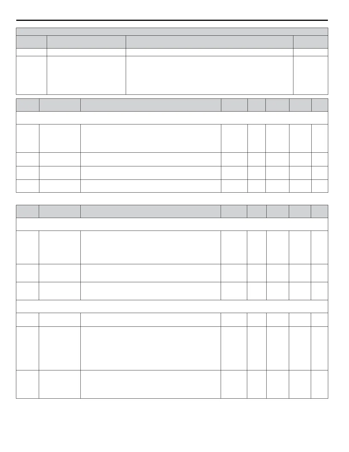
H2 Multi-Function Digital Output Settings
H2-01
Setting
Function Description Page
3D Speed Search Closed: Speed search is being executed 107
100 to 102;
104 to 108;
10B, 10E,
110, 117,
11A, 11E,
13C, 13D
H2 Parameter Functions Reversed
Output Switching of 0 to 13D
Reverse the output switching of the multi-function output functions. Set the last
two digits of 1oo to reverse the output signal of that specific function
Examples:
Setting “108” reverses the output of “During baseblock”, which is setting value
08
Setting
“13C” reverses the output of “LOCAL/REMOTE Status”, which is setting
“3C”
107
No. Name Description Range Def. Mode
Addr.
Hex
Pg.
H3: Analog Input A1
Use H3 parameters to set the analog input terminal A1.
H3-01
Terminal A1
Signal Level
Selection
Sets the input level for terminal A1.
0: 0 to +10 V (lower limit)
1: 0 to +10 V (no lower limit)
2: 4 to 20 mA
3: 0 to 20 mA
0 to 3 0 O 410 107
H3-03
<1>
Terminal A1 Gain
Setting
Sets the level of the input value when 10 V (20 mA) is input at
terminal A1.
-999.9 to
999.9
100.0
%
O 411 108
H3-04
<1>
Terminal A1 Bias
Setting
Sets the level of the input value when 0 V (0 or 4 mA) is input at
terminal A1.
-999.9 to
999.9
0.0% O 412 108
H3-13
Analog Input Filter
Time Constant
Sets the primary delay filter time constant for terminal A1 or
potentiometer (optional). Used for noise filtering.
0.00 to 2.00 0.03 s O 41B 110
<1> Parameter can be changed during run.
No. Name Description Range Def. Mode
Addr.
Hex
Pg.
H4: Multi-Function Analog Output AM
Use H4 parameters to configure the multi-function analog output terminal AM.
H4-01
Multi-Function
Analog Output
Terminal AM
Selects the data to be output through multi-function analog output
terminal AM.
Set the desired monitor parameter to the digits available in Uo-
oo. For example, enter “103” for U1-03.
When using this terminal in through mode or when not using it at
all, set “000” or “031”.
000 to 999 102 O 41D 110
H4-02
<1>
Multi-Function
Analog Output
Terminal
AM Gain
Sets terminal AM output level when selected monitor is at 100%.
Maximum output voltage is 10 V.
-999.9 to
999.9
100.0% S 41E 110
H4-03
<1>
Multi-Function
Analog Output
Terminal AM Bias
Sets terminal AM output level when selected monitor is at 0%.
-999.9 to
999.9
0.0% O 41F 110
H5: MEMOBUS/Modbus Communications
Use H5 Parameters to connect the drive to a MEMOBUS/Modbus network (communication option required).
H5-01
<2>
Drive Slave
Address
Selects drive slave number (address) for MEMOBUS/Modbus
communication. Cycle power for the setting to take effect.
0 to FF 1F O 425 214
H5-02
Comm. Speed
Selection
Selects the baud rate for MEMOBUS/Modbus communication.
Cycle power for the setting to take effect.
0 : 1200 bps
1 : 2400 bps
2 : 4800 bps
3 : 9600 bps
4 : 19200 bps
5 : 38400 bps
0 to 5 3 O 426 214
H5-03
Comm. Parity
Selection
Selects the communication parity for MEMOBUS/Modbus
communication. Cycle power for the setting to take effect.
0: No parity
1: Even parity
2: Odd parity
0 to 2 0 O 427 214
B.2 Parameter Table
196
YASKAWA ELECTRIC SIEP C710606 31B YASKAWA AC Drive – J1000 Technical Manual
http://nicontrols.com

 Loading...


