Closed-Loop Crimp Terminal Recommendations
Note: Use crimp insulated terminals or insulated tubing for wiring these connections. Wires should have a continuous maximum allowable
temperature of 75 °C 600 V UL approved vinyl sheathed insulation. Ambient temperature should not exceed 30 °C.
Yaskawa recommends crimp terminals made by JST and Tokyo DIP for the insulation cap.
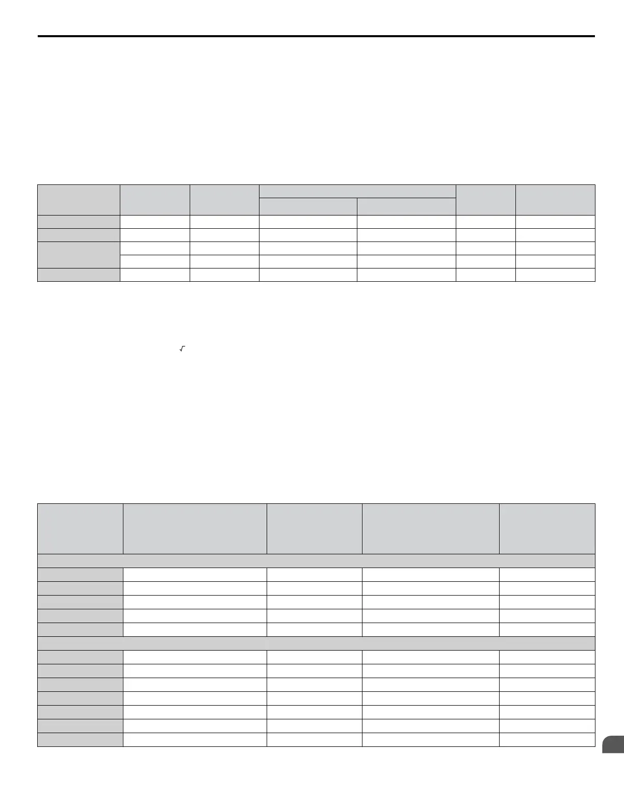
Table D.6 matches the wire gauges and terminal screw sizes with Yaskawa-recommended crimp terminals, tools, and insulation
caps. Refer to the appropriate Wire Gauge and Torque Specifications table for the wire gauge and screw size for your drive
model. Place orders with a Yaskawa representative or the Yaskawa sales department.
The closed-loop crimp terminal sizes and values listed in Table D.6 are Yaskawa recommendations. Refer to local codes for
proper selections.
Table D.6 Closed-Loop Crimp Terminal Sizes
Wire Gauge
Terminal
Screws
Crimp Terminal
Model Number
Tool Insulation
Cap
Model No.
Code
<1>
Machine No. Die Jaw
18 AWG M3.5 R1.25-3.5 YA-4 AD-900 TP-003 100-066-217
16 AWG M3.5 R1.25-3.5 YA-4 AD-900 TP-003 100-066-217
14 AWG
M3.5 R2-3.5 YA-4 AD-900 TP-003 100-066-218
M4 R2-4 YA-4 AD-900 TP-003 100-054-028
12 / 10 AWG M4 R5.5-4 YA-4 AD-900 TP-005 100-054-029
<1> Codes refer to a set of three crimp terminals and three insulation caps. Prepare input and output wiring using two sets for each connection.
Example: Models with 14 AWG for both input and output require one set for input terminals and one set for output terminals, so the user should
order two sets of [100-066-218].
Note: Consider
the amount of voltage drop when selecting wire gauges. Increase the wire gauge when the voltage drop is greater than 2% of motor
rated voltage. Ensure the wire gauge is suitable for the terminal block. Use the following formula to calculate the amount of voltage drop:
Line drop voltage (V) =
3 × wire resistance (Ω/km) × wire length (m) × current (A) × 10
-3
n
Factory Recommended Branch Circuit Protection
Yaskawa
recommends installing one of the following types of branch circuit protection to maintain compliance with UL508C.
Semiconductor protective type fuses are preferred. Alternate branch circuit protection devices are also listed in Table D.7.
Branch circuit protection shall be provided by any of the following:
• Non-time delay Class J, T, or CC fuses sized at 300% of the drive input rating
Note: The following model/fuse combinations are excluded from the preceding statement: 2A0002/A6T6, 2A0004/A6T15,
4A0004/A6T15, 4A0005/A6T20, and 4A0007/A6T25.
• Time delay Class J, T, or CC fuses sized at 175% of the drive input rating
• Time-delay Class RK5 fuses sized at 225% of the drive input rating
Table D.7 Factory Recommended Drive Branch Circuit Protection
Drive Model
CIMR-Jo
Non-Time Delay
Class T Fuse Type
(Manufacturer: Ferraz)
Rated Voltage:
600 Vac, 200 kAIR
Fuse Ampere Rating
(A)
Fuse Type
(Manufacturer: Bussmann)
Rated Voltage:
500 Vac, 200 kAIR
Fuse Ampere Rating
(A)
200 V Class Single-Phase Drives
BA0001 A6T6 6 FWH-25A14F 25
BA0002 A6T10 10 FWH-25A14F 25
BA0003 A6T20 20 FWH-60B 60
BA0006 A6T40 40 FWH-80B 80
BA0010 A6T40 40 FWH-100B 100
200 V Class Three-Phase Drives
2A0001 A6T3 3 FWH-25A14F 25
2A0002 A6T6 6 FWH-25A14F 25
2A0004 A6T15 15 FWH-25A14F 25
2A0006 A6T20 20 FWH-25A14F 25
2A0010 A6T25 25 FWH-70B 70
2A0012 A6T25 25 FWH-70B 70
2A0020 A6T40 40 FWH-90B 90
D.3 UL Standards
YASKAWA ELECTRIC SIEP C710606 31B YASKAWA AC Drive – J1000 Technical Manual
243
D
Standards Compliance
http://nicontrols.com

 Loading...


