10.3 7 SEG-LED Indicator
10-3
10.3 7 SEG-LED Indicator
The following tables show the operating statues for JANCD-NIF01/SGDR-AXA01/SGDR-
AXA02/JANCD-NCP02. The operating statuses are indicated by 7 SEG-LED.
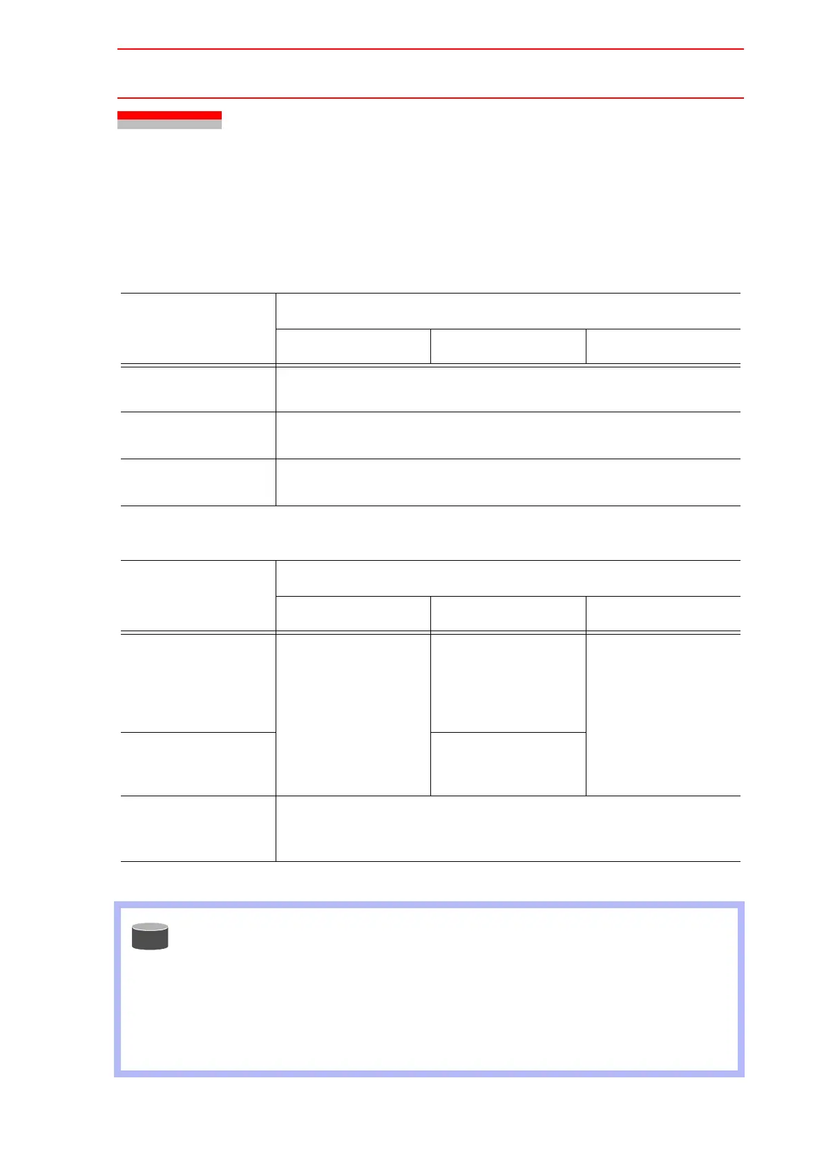
[Normal Indication]
[Error Indication]
Status
NX100
NIF Circuit Board AXA Circuit Board NCP02 Circuit Board
Right after applying
the power
All 7-SEG indicators light up.
(‘8’, ‘+’, ‘.’ light up.)
During the start-up
process
Counts up from ‘O’ toward ‘d’.
After starting up nor-
mally
‘d’, ‘+’, ‘.’ blink every one second.
Status
NX100
NIF Circuit Board AXA Circuit Board NCP02 Circuit Board
Alarms occurrence in
the Main CPU and
servo CPU communi-
cation system
‘d’, ‘+’, ‘.’ blink every
one second.
The error cause is
indicated by 7 SEG-
LED.
(See the indication
spec
.)
‘d’, ‘+’, ‘.’ blink every
one second.
Normal alarms other
than alarms described
above
‘d’, ‘+’, ‘.’ blink every
one second.
Fatal alarms occur-
rence
The error cause and the address where the error has occurred are indi-
cated by 7 SEG-LED.
(See the indication spec
.)
Indication Spec
E.g.)
The cycle: [F] [0] [0] [3] [.] is repeated.
: Error cause
Indication Spec
E.g.)
[-] [0] [2] [0] [0]
The cycle: [,] [-] [0] [0] [0] [0] [F]
[F] [0] [4] is repeated.
: Error cause
: Address where the error occurred
SUPPLE-
MENT

 Loading...


