5.1 Replacing NX100 Parts
5-4
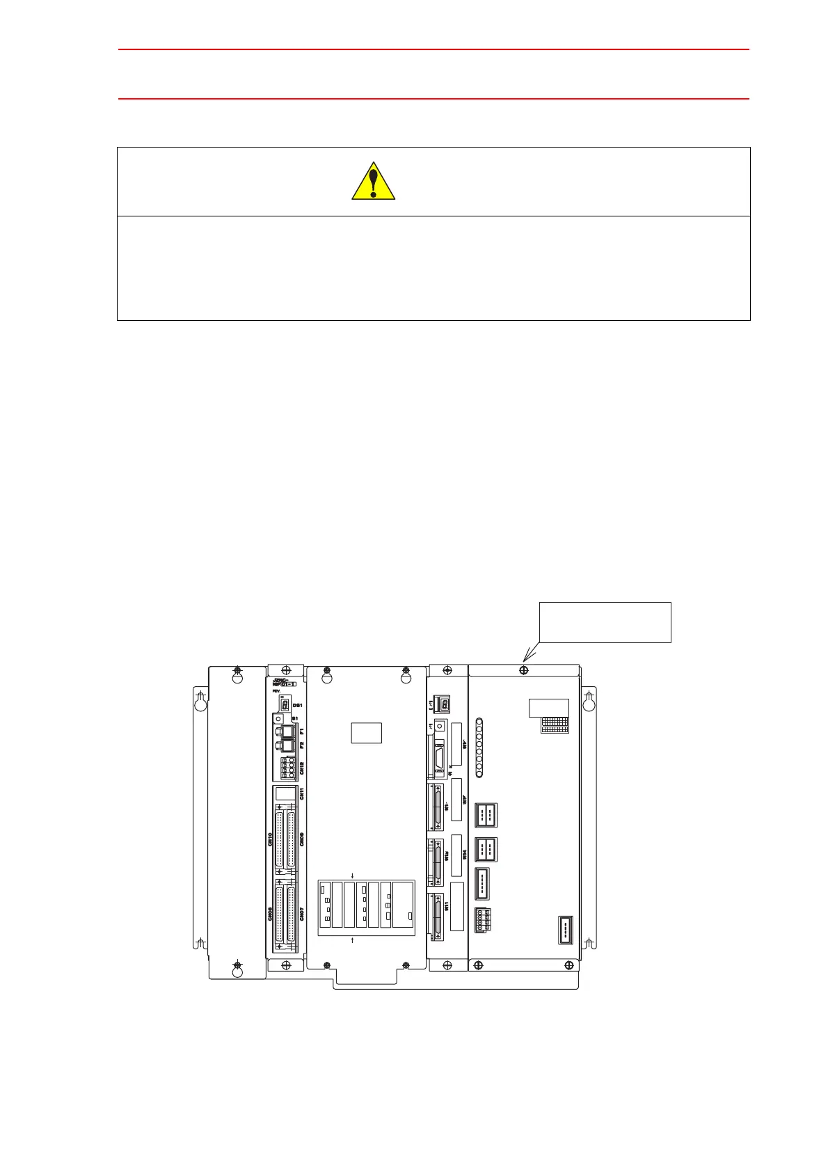
Replacing the Control Power Supply (CPS-420F)
Replacement Procedure
1. Disconnect all cables connected to the control power supply.
2. Loosen four upper and lower screws attaching the control power supply and the rack.
(two screws on each side).
3. Pull out the control power supply from the rack holding the grips which are attached at
the upper and lower side.
4. Insert the new control power supply into the slot of the rack.
5. Push the new control power supply until it is placed in the same position of other
boards.
6. Tighten upper and lower screws.
7. Connect all disconnected cables.
• After turning OFF the power supply, wait at least 5 minutes before
replacing a control power supply. Do not touch any terminals during this
period. Confirm all monitor lights are turned OFF.
Failure to observe this caution may result in electric shock or injury.
CAUTION
KJH
VUT
28 29 30
08 09 10
18 19 20
GFEDC
SRQPN
Co.,Ltd.
23 24 25 26
03 04 05 06
13 14 15 16
JAPAN
27
07
17
BA
ML
DATE
Fuji
21
01
11
No.
POWER
CPS-NX1
Electric
22
02
12
SUPPLY
LAN0 COM
Front side
CN3
CN1
Bottom connector view
CPS-420
CN6
LAN1
CPUPCI PCI
EXT
CN1
AXIS
CN2
CN2CN1
PCINIF
Rear side
CN3
Option PCI Slot #CPU2
Option PCI Slot #CPU1
Option PCI Slot #AXIS
+5VSB
+5V
+24V
OTHER
FAN
PON
CN05
(+24V1)
CN04
(+24V2)
OHT
SOURCE
CN01
(AC IN)
INPUT
3A
50/60Hz
200-240V AC
(TU)
CN03
(REMOTE)
CN02
CPS-420F
Control power supply

 Loading...


