1.1 Arrangement of Units and Circuit Boards
1-1
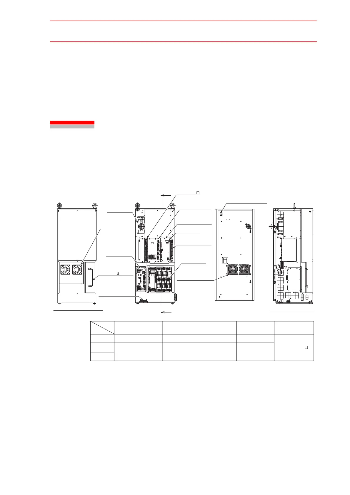
1 Equipment Configuration
The NX100 is comprised of individual units and modules (circuit boards). Malfunctioning com-
ponents can generally be easily repaired after a failure by replacing a unit or a module. This
section explains the configuration of the NX100 equipment.
1.1 Arrangement of Units and Circuit Boards
The arrangements of units and circuit boards in small-capacity, medium-capacity, and large-
capacity NX100s are shown.
Small Capacity
Configuration 1 for Small-Capacity NX100
Sectional View A-A'
Emergency stop button:
AR22V2R-04R
Major axes control
circuit board:
SGDR-AXA01A
Control power supply:
CPS-420F
Robot I/F unit:
JZNC-NIF01
Welding circuit board:
JANCD-XEW02
CPU unit:
JZNC-NRK01
SERVOPACK:
Refer to the
following table.
Interior circulation fan:
4715MS-22T-B50-B00
Breaker:
Refer to the
following table.
Backside duct fan:
4715MS-22T-B50-B00
(For air inlet)
Regenerative resistor:
MRC22-125K-220W-12.5
(220W,12.5 )
Power supply
contactor unit:
Refer to the
following table
A
A'
(MXT)
Robot system input
terminal block
Back View
(Air flows up)
(with removed cover)
Breaker
NF30SW 3P 10A
NX100
Model
HP6
ERCR-EA1400N-AA00
EA1400N
SGDR-EA1400N
SERVOPACK
(Converter Integrated)
Power Supply
Contactor Unit
JZRCR-NTU01 -1
Type
HP3
ERCR-HP3-AA00
SGDR-EA1400NY26
NF30SW 3P 5A

 Loading...


