5.1 Replacing NX100 Parts
5-5
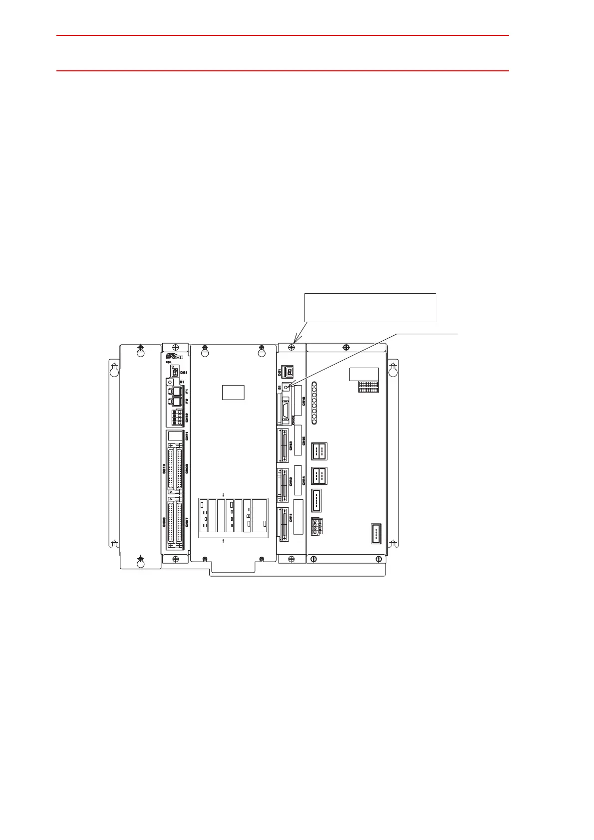
Replacing the Servo Control Circuit Board (SGDR-AXA01A)
Turn OFF the power before replacing a servo control circuit board.
Replacement Procedure
1. Disconnect all cables connected to the servo control circuit board. (Be sure to remove
the connectors at the bottom of the board.)
2. Remove 2 screws fixing the servo control circuit board and rack.
3. Pull out the servo control circuit board from the rack.
4. Insert a new board into the slot of the rack.
5. Tighten upper and lower screws.
6. Connect all disconnected cables.
7. Set the rotary switch to the same value as the removed board’s rotary switch.
KJH
VUT
28 29 30
08 09 10
18 19 20
GFEDC
SRQPN
Co.,Ltd.
23 24 25 26
03 04 05 06
13 14 15 16
JAPAN
27
07
17
BA
ML
DATE
Fuji
21
01
11
No.
POWER
CPS-NX1
Electric
22
02
12
SUPPLY
LAN0 COM
Front side
CN3
CN1
Bottom connector view
CPS-420
CN6
LAN1
CPUPCI PCI
EXT
CN1
AXIS
CN2
CN2CN1
PCINIF
Back side
CN3
Option PCI Slot #CPU2
Option PCI Slot #CPU1
Option PCI Slot #AXIS
+5VSB
+5V
+24V
OTHER
FAN
PON
CN05
(+24V1)
CN04
(+24V2)
OHT
SOURCE
CN01
(AC IN)
INPUT
3A
50/60Hz
200-240V AC
(TU)
CN03
(REMOTE)
CN02
Rotary switch
Servo control circuit board
SGDR-AXA01A

 Loading...


