5.1 Replacing NX100 Parts
5-3
Replacing the Battery
Replace the battery immediately if a battery alarm occurs. Replace the battery within two
hours after the breaker turns OFF.
(The battery alarms appear on the programing pendant display.)
Replacement Procedure
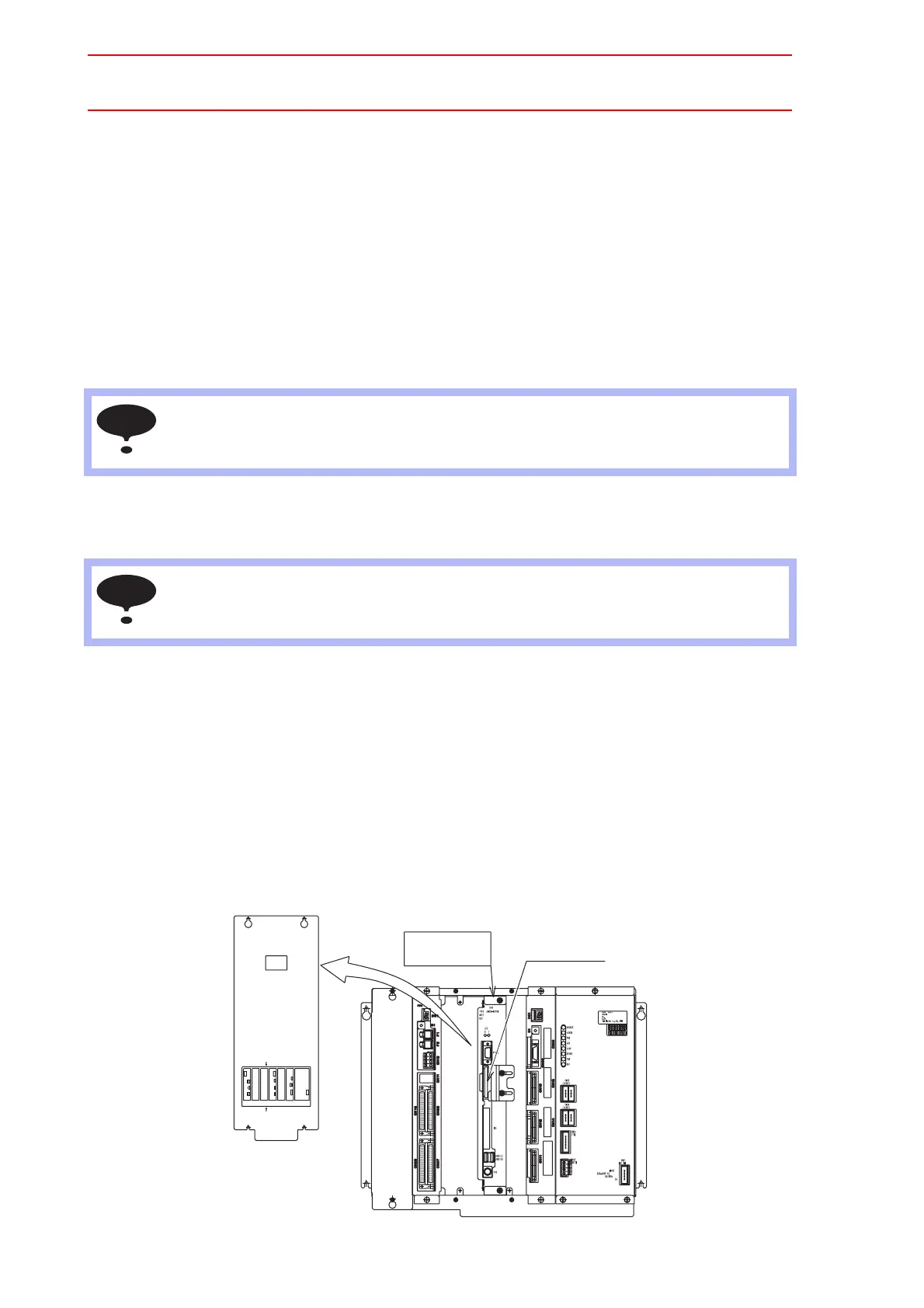
1. Remove the left cover of the CPU unit.
2. Remove the battery connector (BAT) on the back board on the left of the CPU unit.
3. Remove the battery from the rack frame.
4. Mount a new battery on the rack frame and connect the battery connector (BAT) on the
back board.
Replacing the Control Circuit Board (JANCD-NCP01)
Turn OFF the power before replacing a circuit board.
Replacement Procedure
1. Disconnect all cables connected to the circuit board. (Be sure to remove the connec-
tors at the bottom of the circuit board.)
2. Remove 2 screws fixing the circuit board and rack.
3. Pull out the circuit board from the rack.
4. Remove the Compact Flash from the removed circuit board and insert the Compact
Flash into a new circuit board.
5. Mount the new circuit board to the rack.
6. Tighten upper and lower screws.
7. Connect all disconnected cables.
Although the CMOS memory is backed up by super capacitor, the battery must be
replaced as soon as the battery alarm occurs. The job data and other data may be lost if
the battery alarm occurs and the breaker is turned OFF for more than 2 hours.
The JANCD-NCP01 circuit board contains important file data for the user programs, which
is backed up by the battery. Incorrect operations can cause this stored file data to be lost.
NOTE
NOTE
LAN0 COM
Front side
CN3
CN1
Bottom connector view
CPS-420
CN6
LAN1
CPUPCI PCI
EXT
CN1
AXIS
CN2
CN2CN1
PCINIF
Rear side
CN3
Option PCI Slot #CPU2
Option PCI Slot #CPU1
Option PCI Slot #AXIS
Control circuit board
JANCD-NCP01
Cover
Compact flash

 Loading...


