10 Appendix
10.1.2 Parameters
10-18
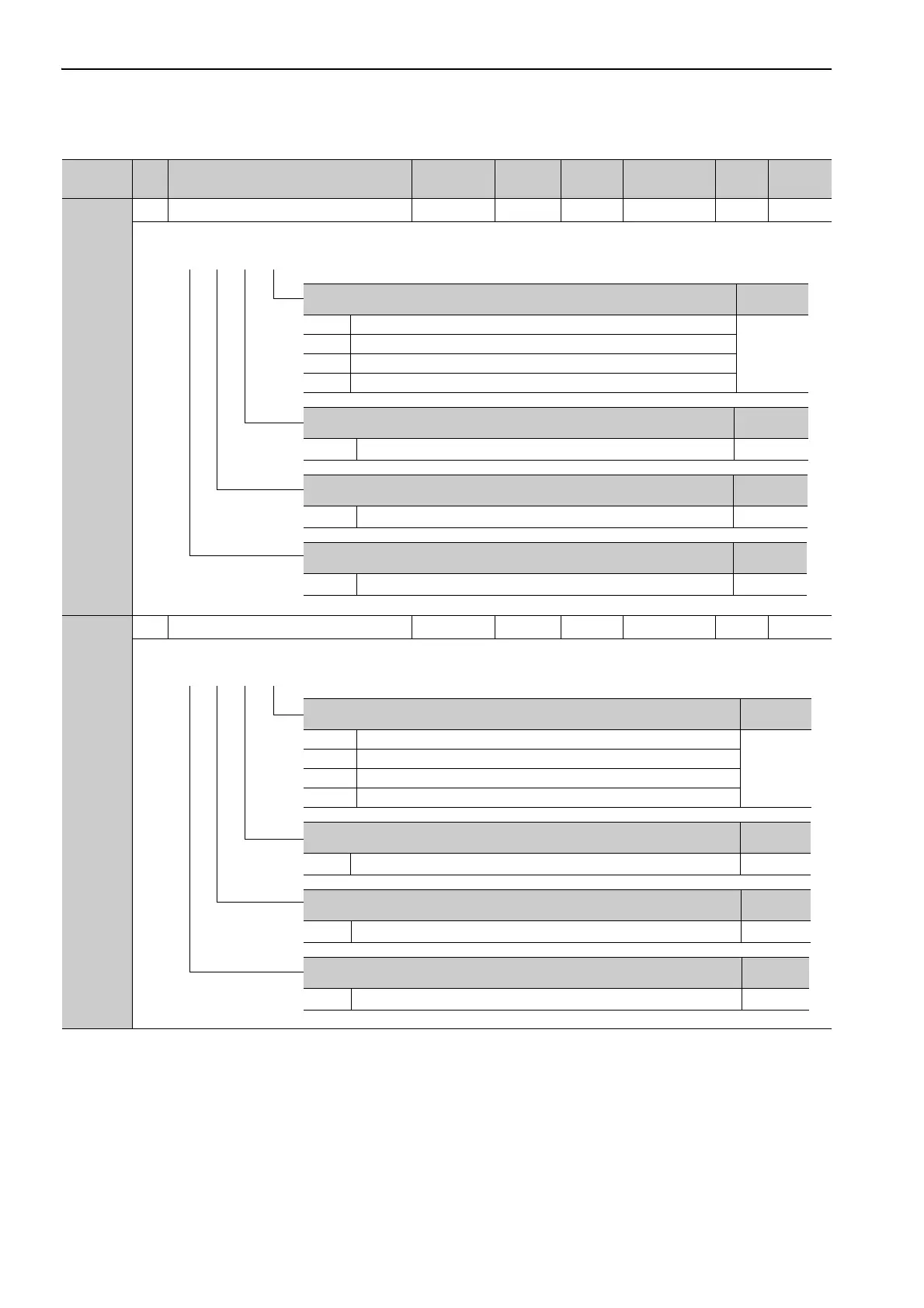
Pn50E
2 Output Signal Selection 1 0000 to 3333 − 0000 After restart Setup −
Pn50F
2 Output Signal Selection 2 0000 to 3333 − 0100 After restart Setup −
(cont’d)
Parameter
No.
Size
Name
Setting
Range
Units
Factory
Setting
When
Enabled
Classi-
fication
Reference
Section
Positioning Completion Signal Mapping (/COIN)
Reference
Section
0 Disabled (the above signal is not used.)
4.6.6
1 Outputs the signal from CN1-25, -26 output terminal.
2 Outputs the signal from CN1-27, -28 output terminal.
3 Outputs the signal from CN1-29, -30 output terminal.
Speed Coincidence Detection Signal Mapping (/V-CMP)
Reference
Section
0 to 3
Same as /COIN Signal Mapping.
4.6.5
Servomotor Rotation Detection Signal Mapping (/TGON)
Reference
Section
0 to 3
Same as /COIN Signal Mapping.
4.6.3
Servo Ready Signal Mapping (/S-RDY)
Reference
Section
0 to 3
Same as /COIN Signal Mapping.
4.6.4
4th 3rd 2nd 1st
digit digit digit digit
n.
Torque Limit Detection Signal Mapping (/CLT)
Reference
Section
0 Disabled (the above signal is not used.)
4.4.3
1 Outputs the signal from CN1-25, -26 output terminal.
2 Outputs the signal from CN1-27, -28 output terminal.
3 Outputs the signal from CN1-29, -30 output terminal.
Speed Limit Detection Signal Mapping (/VLT)
Reference
Section
0 to 3
Same as /CLT Signal Mapping.
4.6.8
Brake Signal Mapping (/BK)
Reference
Section
0 to 3
Same as /CLT Signal Mapping.
4.2.7
Warning Signal Mapping (/WARN)
Reference
Section
0 to 3
Same as /CLT Signal Mapping.
4.6.2
4th 3rd 2nd 1st
digit digit digit digit
n.

 Loading...


