3 - 7
IM 4H3B1-01E
3. INSTALLATION
3.2 Wiring
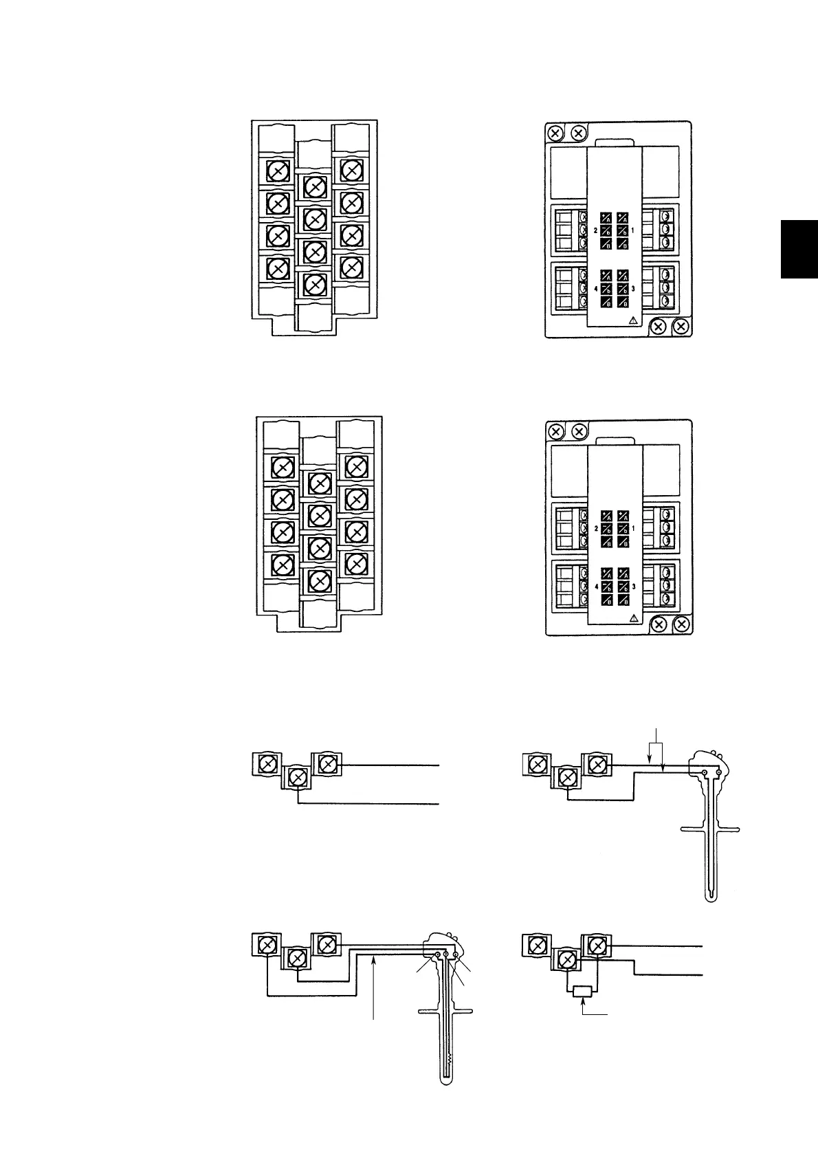
Clamped Input Terminal (/H2 option)
A
A
Leadwire resistance:
10Ω max./leadwire
Three wire resistances
should be approx. equal.
+
–
+
–
Shunt resistor
NOTE: For 4 to 20mA input, shunt resistance
value should be 250Ω ±0.1%.
DC current input
B
b
B
b
Figure 3.8 Wiring Input Terminals in case of Pen Model
+
+
–
–
DC voltage input
Compensation lead
+
–
Resistance Temperature Detector Input DC Current Input
DC Voltage Input/DI Input (contact)
Thermocouple Input
1 ch.
2 ch.
3 ch.
4 ch.
+
–
Standard Input Terminal Clamped Input Terminal (/H2 option)
1 ch.
2 ch.
3 ch.
4 ch.
A
b
B
Figure 3.6 DC V, Thermocouple and Contact Input in case of Pen Model
Standard Input Terminal
Figure 3.7 Resistance Temperature Detector Input in case of Pen Model
+
–
+
+
–
–
–
2 ch.
+
4 ch. 3 ch.
1 ch.
A
b
B
A
b
B
A
b
B
2 ch.
A
b
B
1 ch.
3 ch.
4 ch.
max. wiring ø ≤ 2.5mm
max. wiring ø ≤ 2.5mm
Pen Model

 Loading...