8 - 3
IM 4H3B1-01E
8. AUXILIARY SETTINGS (AUX)
8.1.2 How to Set Zone Recording
Zone recording enables you to define different bands (zones) for each channel, so the
recording traces will not overlap during analog recording.
The initial value is ‘0 to 180mm’.
To set the zones, proceed as follows:
MENU:
SETTING PROCEDURE:
Press the MENU-key for three seconds to enter the SET mode.
Select the ‘SET=AUX’ display using the UP/DOWN-keys, and
press the ENT-key.
Select the ‘MODE=ZONE’ display using the UP/DOWN-keys.
Then press the ENT-key.
Select the desired channel using the UP/DOWN-keys, and press
the ENT-key.
Then specify the left boundary value using the UP/DOWN and the
RIGHT-keys. On the chart paper this left boundary value will
correspond with the left span value. (For example, if your channel
2 has a recording span of –2V to 2V, and you specify the zone to
start from 30mm, then the recording at 30mm will correspond with
the value of –2V.) Then press the ENT-key.
Note that the minimum width of a zone is 5mm. The left boundary
must be less than the right boundary.
Then specify the right boundary value using the UP/DOWN and
the RIGHT-keys, and press the ENT-key.
Note that scales will only be printed for 40mm and bigger zones.
The setting is completed. Press the ENT-key to return to the
‘02:ZONE LEFT=...mm’ display, or press the ESC-key to go to
the ‘SET=AUX’ display; or press the MENU-key for three
seconds to return to the Operation mode.
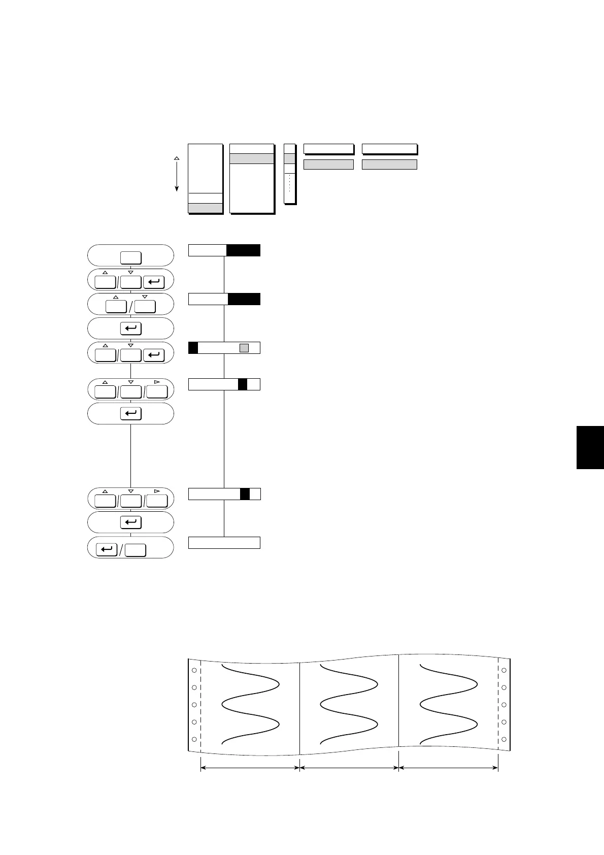
EXPLANATION:
The next figure shows the recording after zone recording has been set (example).
Figure 8.1 Zone Recording Example
8.1 Settings for Analog Recording
Zone 1 Zone 2 Zone 3
ZONE LEFT
30 m m
ZONE RIGHT
50 m m
RANGE
ALARM
UNIT
CHART
CLOCK
COPY
AUX
TREND
ZONE
PART
PRINT
TAG
MSG
CHART 2
01
02
03
24
ALARM
ACK
PRINT
ALARM
ACK
PRINT
ALARM
ACK
SET=AUX
MODE=ZONE
02 :ZONE LEFT= mm
ESC
MENU
PRINT
3sec
SET OK
**
MENU
ESC
3sec
02:ZONE LEFT= mm
30
02:ZONE RIGHT=
mm
50
PRINT
ALARM
ACK
FEED
PRINT
ALARM
ACK
FEED

 Loading...