7 - 7
IM 4H3B1-01E
7.1 How to Set Input Range and Recording Span
7. BASIC SETTINGS
7.1.6 Scale Setting (SCL Setting)
To assign a different scale to the measured data, the range can be set as described
below. Note that the measured data which can get a different scale must be of the
voltage (VOLT), Thermocouple (TC) or Resistance Temperature Detector (RTD) type.
To assign a unit to this new scale, refer to UNIT setting (7.3).
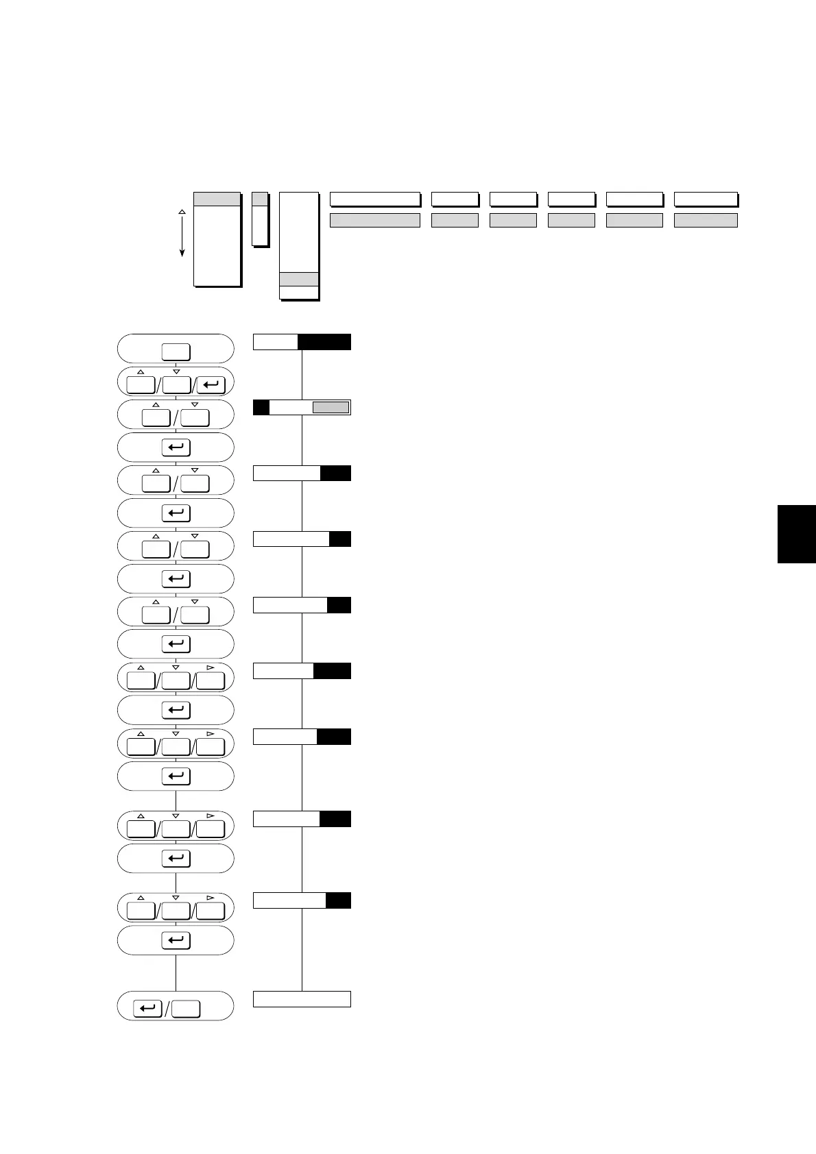
MENU:
SETTING PROCEDURE:
Press the MENU-key for three seconds to enter the SET mode.
Select the ‘SET=RANGE’ display by using the UP/DOWN-keys.
Then press the ENT-key.
Use the UP/DOWN-keys to select the desired channel.
Press the ENT-key.
Use the UP/DOWN-keys to select ‘SCL’.
Press the ENT-key.
Select the input type using the UP/DOWN-keys and press the
ENT-key.
Select the desired range (using the UP/DOWN-keys) and press the
ENT-key.
Set the minimum value of the recording span using the UP/
DOWN and RIGHT-keys. Then press the ENT-key.
Set the maximum value of the recording span using the UP/
DOWN and RIGHT-keys. Then press the ENT-key. Note that the
decimal point will be in the same position as for LEFT. LEFT
cannot be equal to RIGHT.
Set the minimum value of the scale corresponding to the minimum
value of the recording span using the UP/DOWN and the RIGHT-
keys. Note that the allowable range is –20000 to 20000. Then press
the ENT-key.
Set the maximum value of the scale corresponding to the
maximum value of the recording span. Select it the same way as
the minimum value. Then press the ENT-key. Note that the
decimal point will be in the same position as for SCL LEFT. SCL
LEFT cannot be equal to SCL RIGHT.
The setting is completed.
Press the ENT-key to return to the ‘01:MODE=SCL’ display; or
press the ESC-key to go to the ‘SET=RANGE’ display; or press
the MENU-key for three seconds to return to the Operation mode.
NOTE In this example, 0.000V input will be scaled to –100.0. 2.000V input will be scaled to 100.0.
VOLT
RANGE
2V
LEFT
0.000
RANGE
ALARM
UNIT
CHART
CLOCK
COPY
AUX
01
02
03
04
SKIP
VOLT
TC
RTD
DI
DELT
SCL
SQRT
RIGHT
2.000
SCL LEFT
–100.0
SCL RIGHT
100.0
SCALING MODE
01:MODE=
SET=RANGE
MENU
ESC
01:LEFT=0.000
01:MODE=SCL
01:SCALING MODE=VOLT
01:RANGE=2V
2.00001:RIGHT=
01:SCL LEFT=–100.0
01:SCL RIGHT=100.0
SET OK
**
3sec
PRINT
ALARM
ACK
PRINT
ALARM
ACK
PRINT
ALARM
ACK
PRINT
ALARM
ACK
PRINT
ALARM
ACK
MENU
ESC
3sec
PRINT
ALARM
ACK
FEED
PRINT
ALARM
ACK
FEED
PRINT
ALARM
ACK
FEED
PRINT
ALARM
ACK
FEED

 Loading...