6 - 6 IM 4H3B1-01E
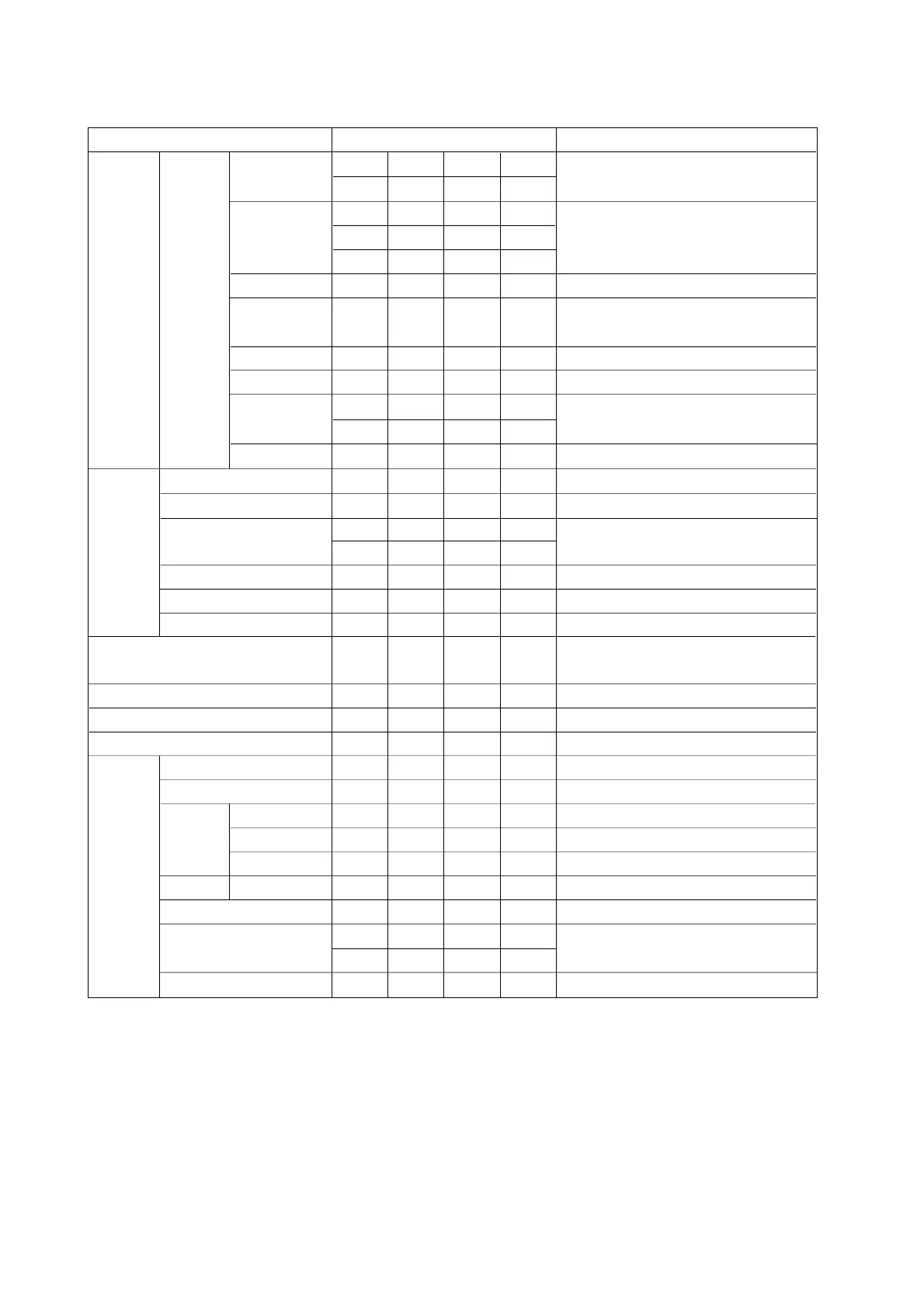
6.4 Setting Parameters in SET Mode
RANGE
MODE
Setting Parameters Values Remarks
VOLT
TC
RTD
DI
DELT
SCL
SQRT
20mV
6V
R
E
W
JPT
LEVL
VOLT
60mV
20V
S
J
L
PT
CONT
TC
200mV
KB
T
U
RTD
2V
N
DC voltage input
Thermocouple input
Input by Resistance Temperature Detector
Digital Input
LEVL: voltage input CONT: contact input
Differential computation
Assigning a different scale
Taking square root of measured data
Assigning unit to scales. Only possible in case of
SCL or SQRT. Max 6 characters.
UNIT
ALARM
LEVEL
Alarm
TYPE
Alarm value
Relay
Relay No.
1234
ON OFF
H
Lh l
Alarm setting ON/OFF
h and l can only be selected in combination
with ‘DELT’ input.
R
r
ON OFF
I01 to I24
Relay 1 to 24, depending on option
Setting chart speed
Setting date and time
Zone recording
Partial compression ON/OFF
Compression rate
Boundary value
Periodic printout ON/OFF
Tag setting, max 7 characters
Max 5 messages, each up to 16 characters
Chart speed for change-on-alarm & remote
CHART
CLOCK
AUX
ZONE
PARTIAL partial
rate
boundary
periodic printoutPRINT
TAG
MESSAGE
Chart speed 2
ON
ON
OFF
OFF
TREND (dot model only)
AUTO
FIX
Selecting analog recording interval
SKIP
20mV
6V
60mV
20V
200mV 2V
Skips a channel
COPY
MSG1 MSG2 MSG3 MSG4
MSG5

 Loading...