3 - 6 IM 4H3B1-01E
!
3.2.3 Input Wiring
1 Make sure the power switch is turned OFF and remove the transparent cover at the
rear of the µR1800.
2 Connect the input wires to the input terminal.
3 Replace the transparent cover.
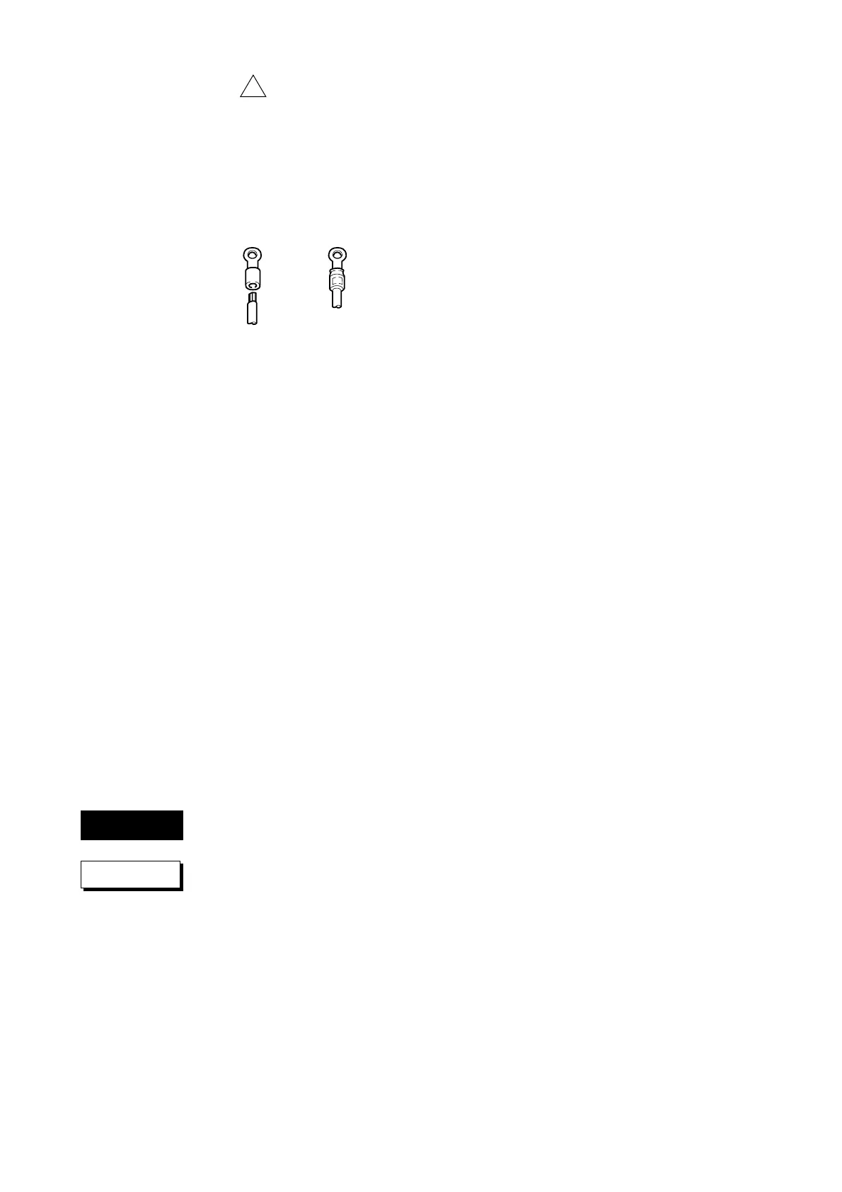
It is recommended that “crimp on” lugs (for 4mm screws) with insulation sleeves be
used for leadwire ends. See figure 3.5.
In case of clamped input terminals, do not use “crimp on” lugs.
Since the input terminal will be affected by changes in temperature (e.g. because of
wind), make sure to replace the transparent cover after wiring.
Even after replacement, take care not to expose the terminals to fans, etc.
Suggestions to minimize noise pickup:
• The measuring circuit wiring should be run as remote as possible from the power
and ground wires.
• It is recommended that shielded wires be used to minimize noise pickup from an
electrostatic induction source. The shielding wire of the cable should be connected
to the µR1800 ground terminal (only one ground line).
• To minimize noise from an electromagnetic induction source, twist the measuring
line cables in short and equal spaces.
• The to be measured object should be free from noise. However, if it isn’t, make
sure the measuring circuit is isolated and the to be measured object is grounded.
If TC and RJC is used, the temperature of the input terminals should be as stable as
possible. Therefore, make sure to use the transparent cover. The thermal capacity of
the wiring should be small (recommended ø ≤ 0.3mm).
Refrain from wiring the input parallel. However, if you do, then
• do not use the burnout function
• ground the equipments at the same point
•turning ON/OFF the power might cause malfunction
• RTD cannot be wired parallel.
To prevent an electric shock, ensure the main power supply is turned OFF
and connect the ground terminal using a class 3 resistance of 100Ω or less.
If you have an input of DC ≤ 2V or a TC, don’t apply an input voltage ex-
ceeding ±10VDC.
Do not apply a max. common mode voltage more than 250VAC rms (50/
60Hz). The recorder and measured values will be adversely affected.
Add following to 'CAUTION'
This instrument complies with Inatallation Category ll.
NOTE To prevent an emission of electromagnetic disturbances, separate the input wires from
the other wires at least 0.1m. Over 0.5m is recommended.
Figure 3.5 “Crimp on” Lugs
CAUTION
WARNING

 Loading...