3 - 10 IM 4H3B1-01E
3.2.5 FAIL/Chart End Wiring
1 Make sure the power switch is turned OFF and remove the transparent cover at the rear
of the µR1800.
2 Connect the FAIL/Chart end output wires to the FAIL/Chart end output terminal.
3 Replace the transparent cover.
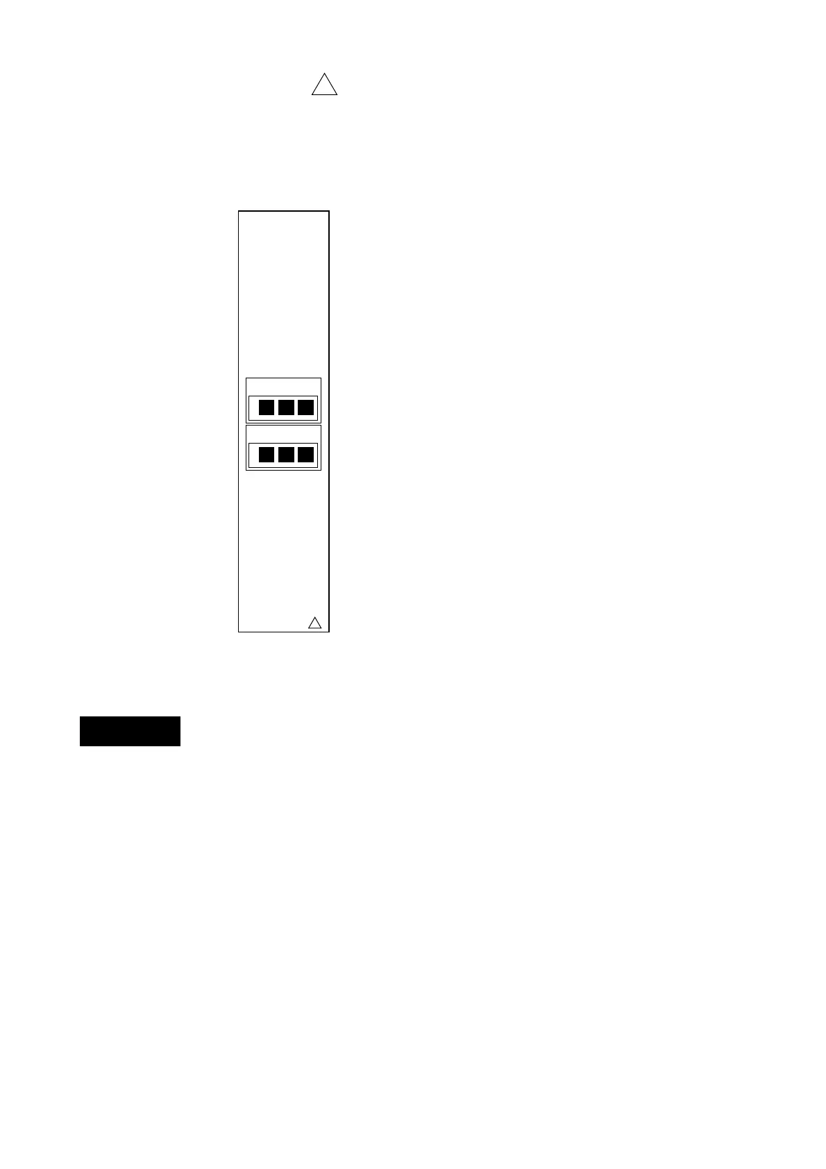
The FAIL/Chart end terminals (option) are arranged as follows:
The FAIL/Chart End output relay is of the de-energize type. See 5.3.9 for details.
• To prevent an electric shock, ensure the main power supply is turned OFF
during wiring and ensure the ground terminal is connected using a class 3
resistance of 100Ω or less.
• Ensure the ground terminal is connected using a class 3 resistance of 100Ω or
less.
• Use "crimp-on" lugs with insulation sleeves for all connections if a voltage of
more than 30 VAC or 60 VDC is applied to the alarm output or fail/memory end
output. Furthermore, use doubleinsulated wires (withstand voltage
performance: more than 2300VAC) for those wires which apply 30 VAC or
60VDC. All other wires can be basic-insulated (withstand voltage performance:
more than 1350VAC). To prevent electric shock, do not touch the terminal after
wiring and make sure to re-attach the cover.
NOTE To prevent an emission of electromagnetic disturbances, separate the FAIL/Chart end
wires from the power supply and input wires at least 0.1m. Over 0.5m is recommended.
Figure 3.13 FAIL/Chart End Output Terminal
!
WARNING
CHART
!
FAIL
NO NCC
NO NCC

 Loading...