3 - 11
IM 4H3B1-01E
3. INSTALLATION
3.2.6 Remote Control Wiring
1 Make sure the power switch is turned OFF and remove the transparent cover at the rear
of the µR1800.
2 Connect the REMOTE output wires to the REMOTE output terminal. Make sure to
connect every terminal with the c(ommon) terminal. Use shielded wires to prevent
electromagnetic interference.
3 Replace the transparent cover.
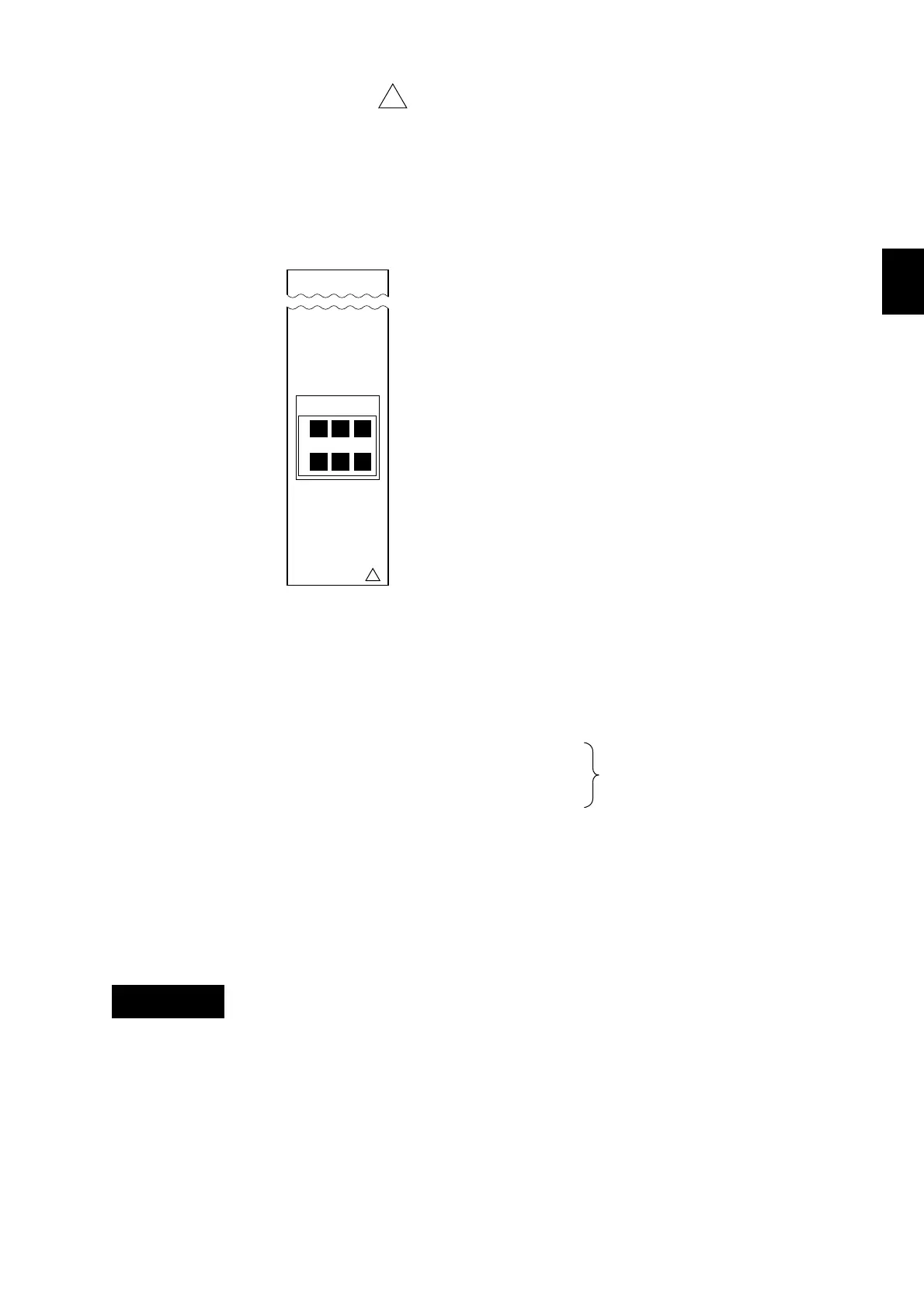
The remote control terminal (option) is arranged as follows:
CHARACTERISTICS:
Input signals: dry contact or open-collector (TTL or transistor)
Input types for each function
(1) recording start/stop level
(2) change chart speed level
(3) start/stop TLOG computation level
(4) printout messages trigger
(5) get a manual printout trigger
(6) get a periodic printout trigger
(7) trigger IC Memory Card trigger
Input conditions: ON voltage (0.5V maximum) (30mA DC)
Leakage current in OFF state (0.25mA maximum)
Signal duration (250 msec minimum)
Input type: Photocoupler isolation (one side common)
Internal isolated power source (5V ±5%)
Dielectric strength: 500VDC between input terminal and ground terminal, 1min.
To adjust initial settings, see 9.8.
To prevent an electric shock, ensure the main power supply is turned OFF
during wiring and ensure the ground terminal is connected using a class 3
resistance of 100Ω or less.
The outer conductor must be grounded at the ground terminal.
NOTE To prevent an emission of electromagnetic disturbances, separate the remote control
wires from the power supply and input wires at least 0.1m. Over 0.5m is recommended.
!
3.2 Wiring
REMOTE
!
132
4C5
Figure 3.14 Remote Control Terminal
WARNING
250 ms minimum

 Loading...