7 - 9
IM 4H3B1-01E
7.1 How to Set Input Range and Recording Span
7. BASIC SETTINGS
F
F
max
F
min
b
b'
a
c
V
V
min
V
max
max
min
(V
– V
) x 1%
(F
max
– F
min
) x 10%
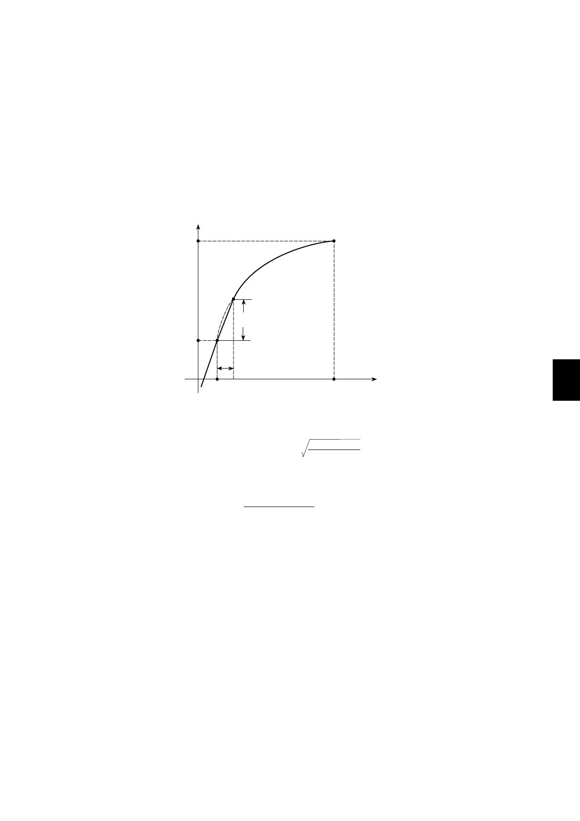
Between b and c in the graph, the following relation exists between F
and V
:
And between a and b, the relation is:
F = (F – F ) + F
x
max
min
V – V
x min
V – V
max
min
min
F = (V – V ) + F
x
x
min
max
min
10 (F – F )
V – V
max
min
min
EXPLANATION OF SQUARE ROOT:
The µR1800 uses the following square rooting-method:
Let us define the items as follows:
V= minimum value of recording span (LEFT)
V= maximum value of recording span (RIGHT)
F= minimum value of scale (SCL LEFT)
F= maximum value of scale (SCL RIGHT)
V= input voltage
F= scaling value
The relationship between V
(input voltage) and F
(scaling value) is as shown in the
graph below (the graph configuration is approximate).
x
x
x
min
max
min
max
x
x
x

 Loading...