Page 4-20 110XiIIIPlus Maintenance Manual 13185L-002 Rev. A 1/24/06
Section 4 Maintenance
4. If an optional interface board is installed in the printer, refer to the removal
instructions Removing the Existing PCMCIA or Wireless PCMCIA Option Board
Assemblies on page 4-128 in this Maintenance Manual before continuing with this
procedure.
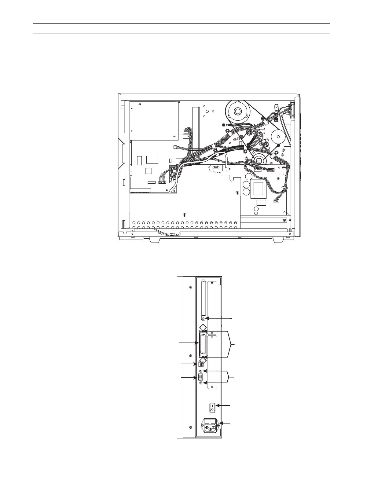
5. Refer to Figure 4-10. Disconnect all connectors from the main logic board.
Figure 4-10. Main Logic Board
6. Refer to Figure 4-11. At the rear of the printer, remove the screws securing the serial
and parallel port connectors.
Figure 4-11. Rear View
PCMCIA
Option Board
AC/DC
Power
PCB
P6
P25
P27
P8
P2
P1
P3
P32
P31
P19
P5
P10
Main Logic
PCB
J4
J3
J1
J5
AC Power
On/Off Switch
AC Power
Cable Connection
Parallel
Interface
Connector
DB-9 Serial
Interface
Connector
Mounting
Studs
Shield Mounting
Screw
Mounting
Screws
USB Connector
 Loading...