13185L-002 Rev. A 1/24/06 110XiIIIPlus Maintenance Manual Page 4-21
Maintenance Section 4
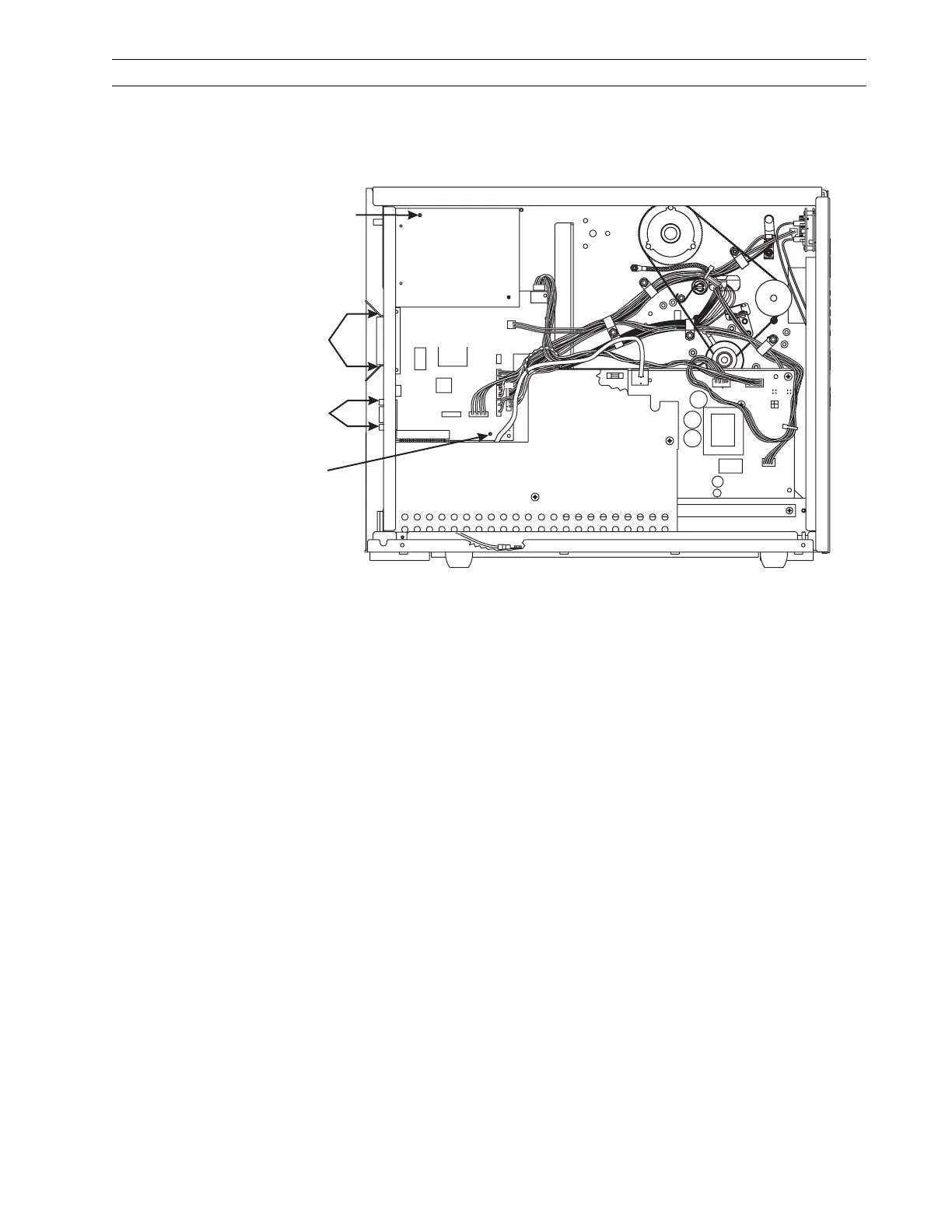
7. Refer to Figure 4-12. Remove the PCMCIA board by first removing the mounting
screw at the upper left of the board, then squeezing the tips of two plastic standoffs
at the lower left and right, and remove the board.
Figure 4-12. Remove and Install the PCMCIA and Main Logic Board
8. Remove the main logic board by removing the mounting screw at the upper right
and the mounting nut at the bottom right.
9. Remove the two standoffs from the main logic board.
Mounting
Screw
Parallel
Connector
Mounting
Screws
Serial
Connector
Mounting
Studs
Mounting
Screw
PCMCIA
Option Board
AC/DC
Power
PCB
P6
P25
P27
P8
P2
P1
P3
P32
P31
P19
P5
P10
Main Logic
PCB
 Loading...