Page 4-72 110XiIIIPlus Maintenance Manual 13185L-002 Rev. A 1/24/06
Section 4 Maintenance
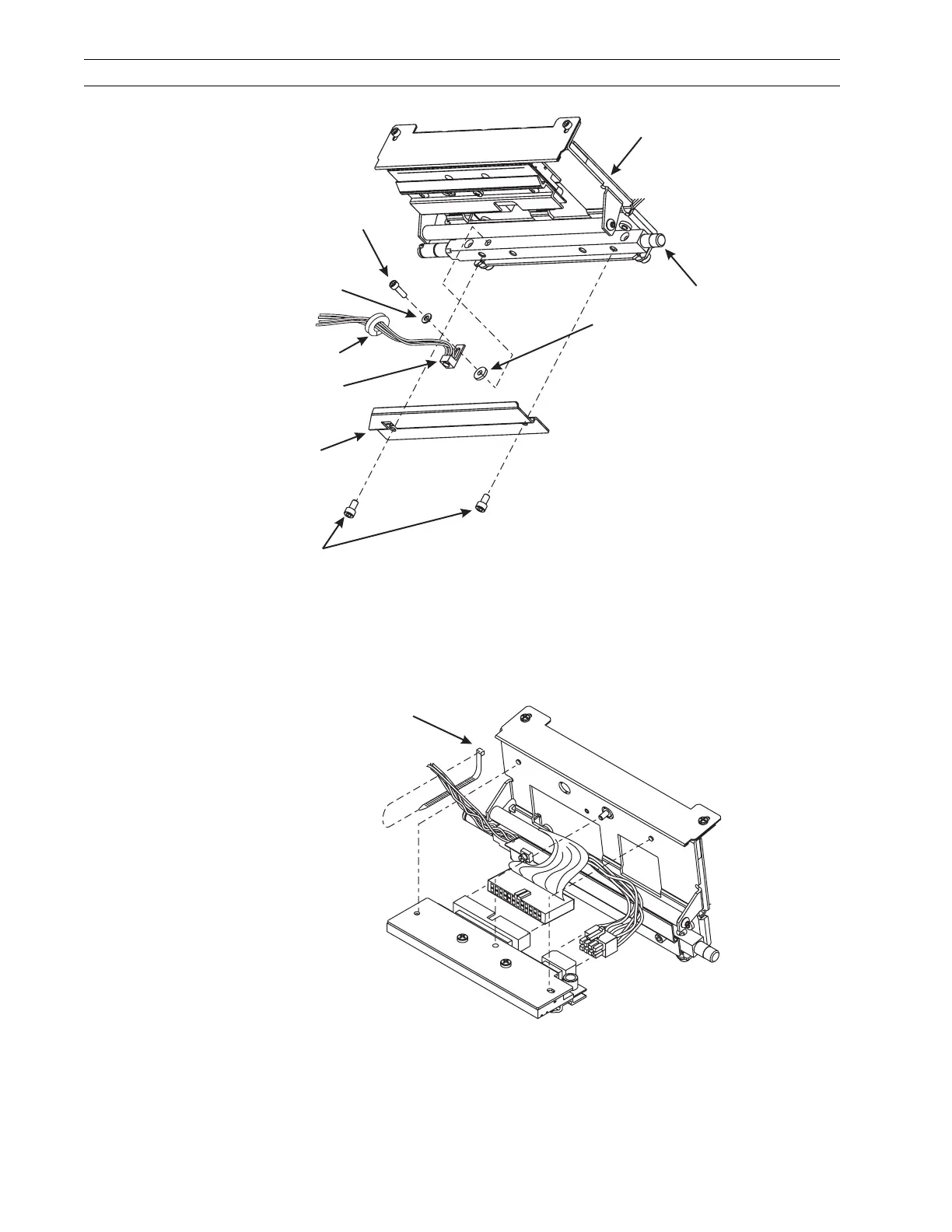
Figure 4-45. Guard Plate and Sensor
9. Pull the data and power cables away from the ribbon sensor.
10. Remove the screw and washer securing the ribbon sensor.
11. Refer to Figure 4-46 and cut the cable tie around the power, data, and ribbon sensor
leads.
Figure 4-46. Remove and Install the Cable Tie
12. Refer to RRP No. 2 on page 4-16 and remove the electronics cover.
Printhead Assembly
Pivot Bar
Screws
Guard Plate
Screw
Flat Washer
Washer
Ribbon Sensor
(See Note.)
Split Grommet
Note • Position the ribbon sensor tab so it is not flush
with the edge of the pivot bar. The gap should be
0.010–0.030 in. (0.3–0.7 mm) below the top edge.
Cable Tie
 Loading...