Page 4-98 110XiIIIPlus Maintenance Manual 13185L-002 Rev. A 1/24/06
Section 4 Maintenance
1. RRP No. 1 on page 4-14. Turn the printer power Off (O) and disconnect the AC
power cord. Disconnect any data cables.
2. RRP No. 2 on page 4-16 and remove the electronics cover.
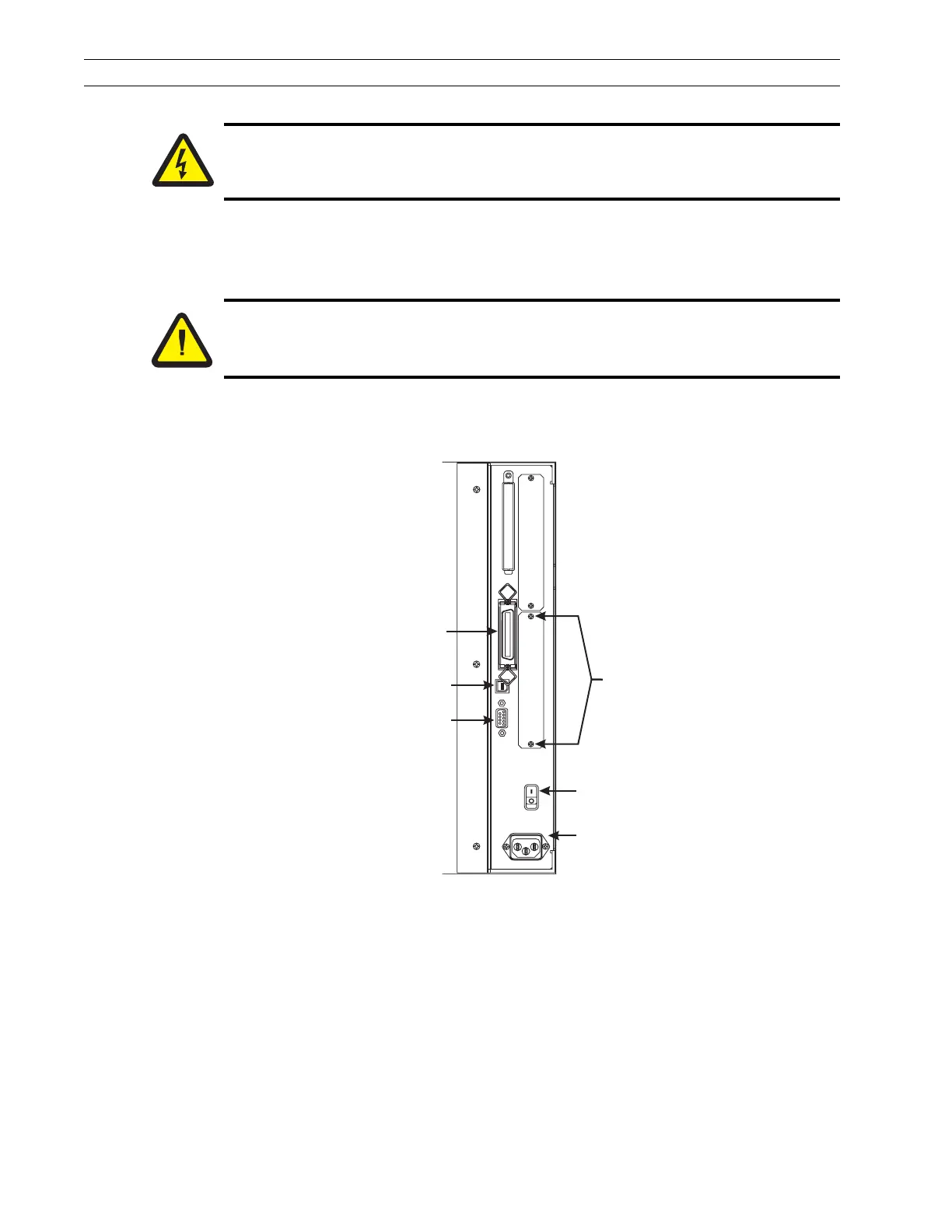
3. Refer to Figure 4-67. At the rear of the printer, remove the two screws and the blank
cover plate or an existing optional interface board positioned next to the main
RS-232 and parallel interface connectors.
Figure 4-67. Cover Plate Rear View
4. Insert the ribbon cable and PrintServer II device through the mounting slot.
5. Refer to Figure 4-68. Fold the cable and the ferrite bead back over the mounting
bracket, and connect the ribbon cable connector into the keyed interface data cable
connector P21 on the main logic board. Ensure the connector is properly seated and
pin 1 of the interface data cable connector is connected to pin 1 of P21.
Caution:
Unless indicated otherwise, turn the printer Off (O) and disconnect the printer
from the power source before performing the following maintenance.
Caution:
This installation must be performed by a qualified service technician.
AC Power
On/Off Switch
AC Power
Cord Connection
Parallel
Interface
Connector
DB-9 Serial
Interface
Connector
USB
Connector
Cover Plate
Mounting
Screws
 Loading...