Page 4-124 110XiIIIPlus Maintenance Manual 13185L-002 Rev. A 1/24/06
Section 4 Maintenance
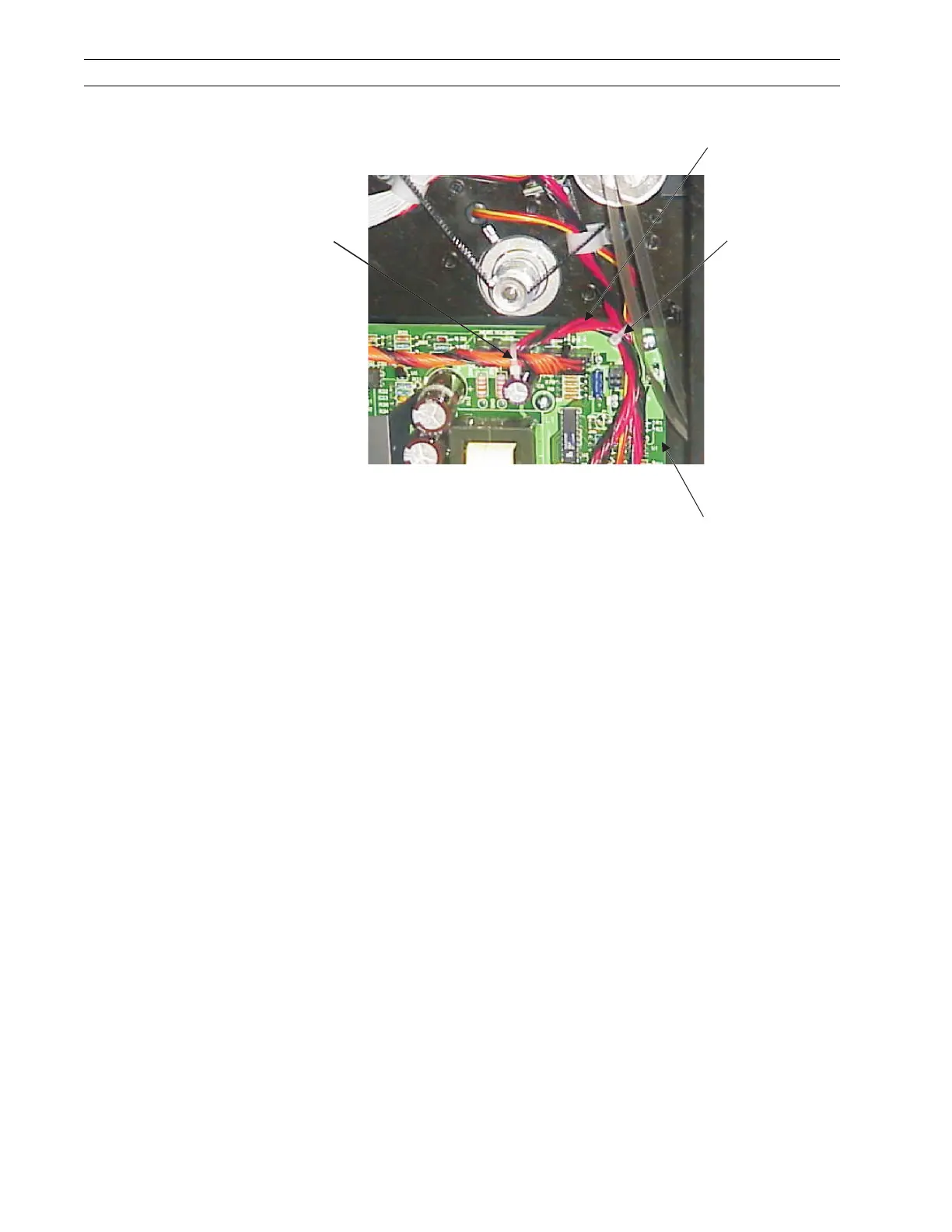
Figure 4-85. Remove the Printhead Power Cable
5. Refer to Figure 4-86. Install the printhead power cable into connector J2 of the
printhead test board.
6. Install the large connector of the supplied short power cable into J1 of the printhead
test board.
7. Install the small connector of the short power cable into the head voltage connector
(J3) on the power supply board.
8. In front of J3 on the power supply board, install a cable tie around the printhead
power cable, the short power cable, and the main logic board power cable as shown
in Figure 4-86.
Cut this
Cable Tie
Printhead
Power Cable
Cut this
Cable Tie
Power
Supply
 Loading...