13185L-002 Rev. A 1/24/06 110XiIIIPlus Maintenance Manual Page 4-125
Maintenance Section 4
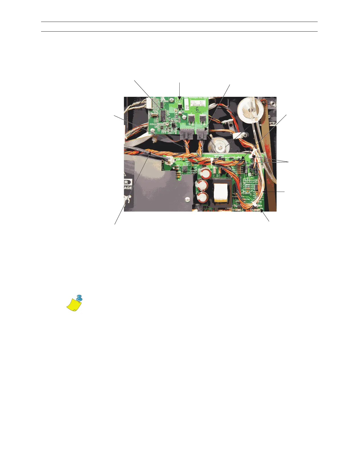
9. In the upper right corner of the power supply board, install a cable tie through the
hole in the board and around the printhead power cable and the stepper motor power
cable, then tighten the cable tie.
Figure 4-86. Install Short Power Cable
10. Refer to Figure 4-87. Connect the SPI (Serial Peripheral Interface) cable to J3 of the
printhead test board.
11. Thread the other end of the cable through the cable tie in the upper left corner of the
power supply board.
Power
Supply
Stepper
Motor
Power
Cable
Cable
Ties
Small
Connector
J3
Printhead
Power Cable
J2
Printhead
Test Board
Large
Connector
J1
Short
Power
Cable
MLB
Power
Cable
Note • If the connector of the SPI cable will not go through the cable tie, you
can open the cable tie, then close and loosely tighten it.
 Loading...