Page 4-126 110XiIIIPlus Maintenance Manual 13185L-002 Rev. A 1/24/06
Section 4 Maintenance
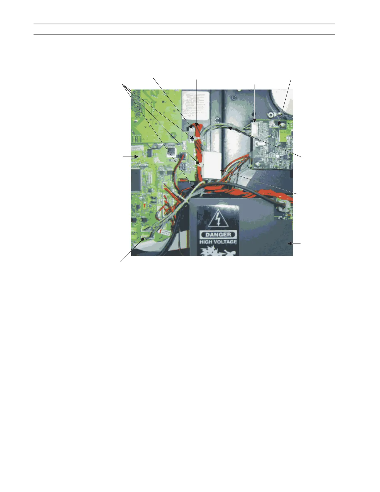
12. Connect the open end of the SPI cable to the SPI connector P35 on the main logic
board (MLB).
Figure 4-87. Install SPI Cable
13. In front of connector P25 of the MLB, bundle the SPI cable and MLB power wires
as shown, then install a cable tie around them.
14. Attach the ferrite block to the MLB power wires as shown in Figure 4-87, using the
cable tie attached to the ferrite block.
15. Open the ferrite block by lifting the lock assembly. Insert all wires of the SPI cable
into the ferrite block, then close it, ensuring it snaps in the locked position.
16. Refer to RRP No. 2 on page 4-16 and reinstall the electronics cover.
17. Reinstall the AC power cord and data cables.
Power
Supply
Ferrite
Block
SPI
Cable
Printhead
Test
Board
SPI Cable
Connector
J3
MLB
Power Wires
P25
Cable Ties
Main
Logic
Board
SPI Cable
Connector
P35
 Loading...