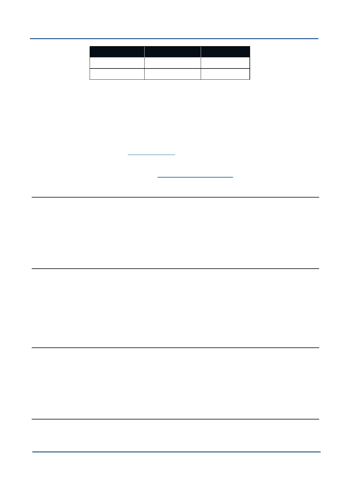
1PPS Source Voltage Level Trigger
Auxiliary -5V to 5V Falling Edge
GPIO 0V to 5V Rising Edge
Figure 76: 1PPSSpecifications
The pin is normally low and pulses high for 50 milliseconds to signal the precise second.
The 1PPS line starts pulsing approximately 100 milliseconds after power up and always
fires irrespective of whether Boreas has accurate time or not. It is important to note that
when Boreas acquires time corrections from it's GNSS receiver, the 1PPS signal may fire
at an interval of less than 1 second. This typically only occurs the first time the GNSS
receiver obtains a fix after startup. The time initialised status flag can be used to
determine whether the time and 1PPS line is accurate or not.
The dedicated 10.3 1PPS Signal on the Connector Pin-out is the recommended 1PPS
signal to use as it comes direct from the internal GNSS receiver rather than the internal
microprocessor. The validity of the dedicated 1PPS signal can be monitored using the
“time initialised” flag in the 11.4.1 System State Packet.
10.6.1.3 GNSS Fix Output
Type:
Digital Output
GPIO Port:
1, 2
Auxiliary:
Transmit
Description
:
In this function, the pin is low when there is no GNSS fix or a 2D fix and high when there is
a 3D, SBAS, Differential or RTK GNSS fix.
10.6.1.4 Zero Velocity Input
Type:
Digital Input
GPIO Port:
1, 2
Auxiliary:
Receive
Description
:
When using this function, a high state indicates to Boreas that it is stationary. The low
state indicates that the vehicle is not stationary. Use of this function can prevent drift
during periods when a GNSS signal is not available.
10.6.1.5 Disable GNSS
Type:
Digital Input
GPIO Port:
1, 2
Auxiliary:
Receive
Description
:
This function accepts a digital input with a low state enabling the GNSS and a high state
disabling the GNSS.
10.6.1.6 Disable Pressure
Type:
Digital Input
v1.2 Page 98 11 Oct 2022
Boreas Reference Manual • Interfacing