R3132 Series Spectrum Analyzer Operation Manual
5.2.7 IF Gain Uncertainty
5-26
Setting the measurement conditions
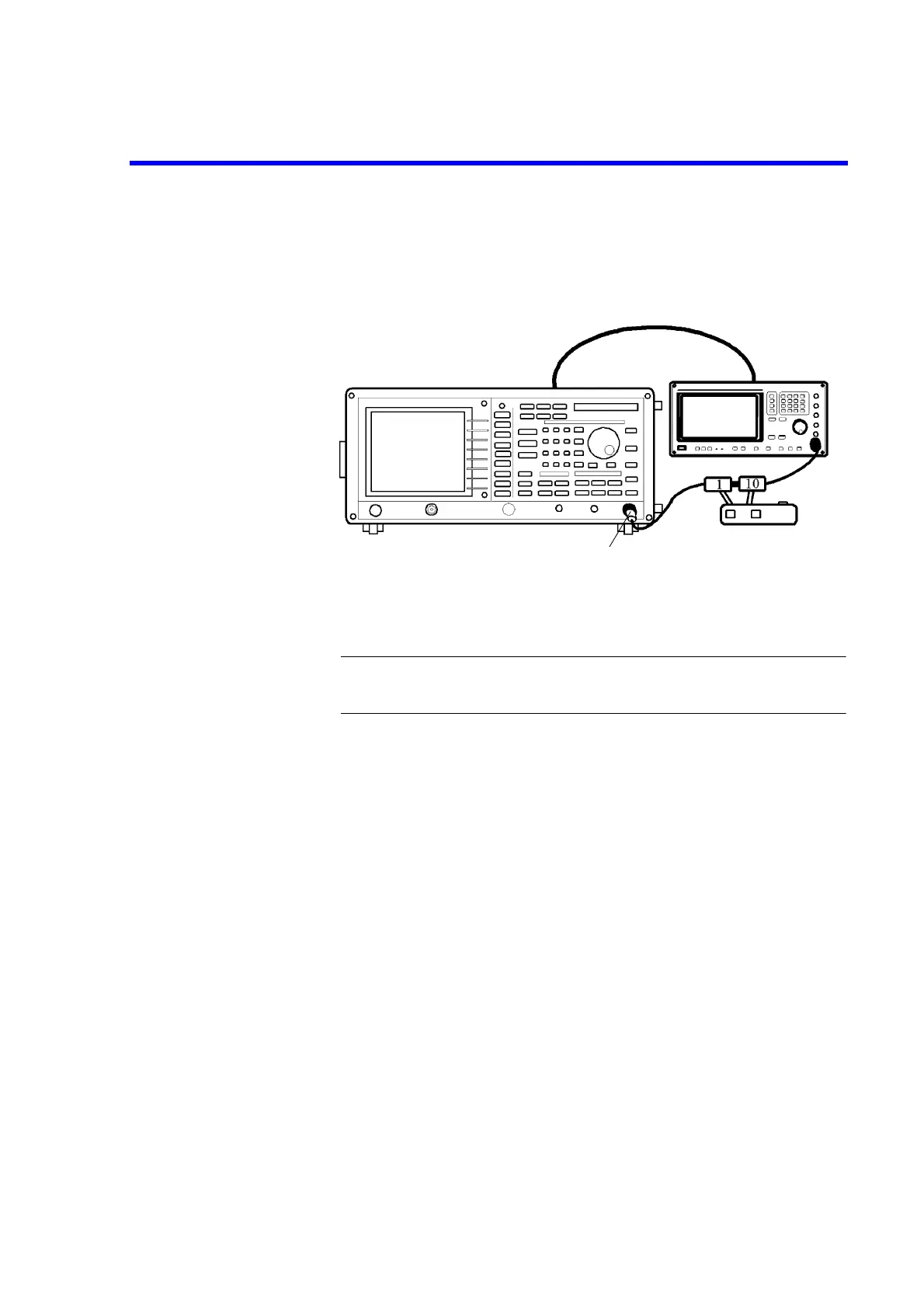
3. On the R3132 series, after AUTO CAL function has completed, connect equip-
ment as shown in Figure 5-7.
Figure 5-7 Setup of IF Gain Uncertainty Test
CAUTION: Use only 75
Ω
ΩΩ
Ω
cables, connectors, or adapters on R3132N, or damage
to the input connector will occur.
4. On the signal generator, set controls as follows:
Frequency: 11 MHz
Output Level: -5 dBm
5. On the 1 dB step attenuator and 10 dB step attenuator, set value 0 dB.
6. On the R3132 series, after preset, set controls as follows:
Center Frequency: 11 MHz
Frequency Span: 2 kHz
Reference Level: 0 dBm
dB/div: 1 dB/div
RBW: 3 MHz
VBW: 10 Hz
Trace Detector: Sample
7. On the signal generator, adjust output level to place the signal 5 dB below the
R3132 series reference level.
8. On the R3132 series, press SINGLE for single sweep.
9. On the R3132 series, after single sweep has completed, press PK SRCH to cap-
ture signal peak and record the marker reading as reference value on the perfor-
mance verification record sheet.
Minimum
Loss Pad (*1)
*1 R3132N only
 Loading...

