R3132 Series Spectrum Analyzer Operation Manual
5.2.19 Gain Compression
5-79
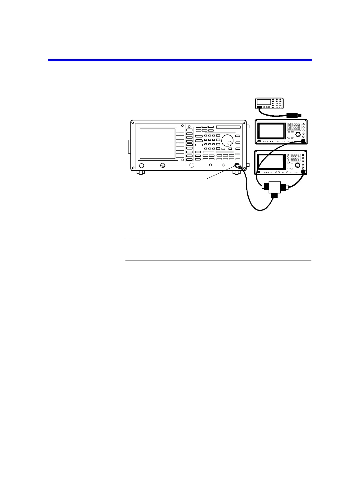
3. Connect the signal generators as shown Figure 5-19.
Figure 5-19 Setup of Gain Compression Test
CAUTION: Use only 75
Ω
ΩΩ
Ω
cables, connectors, or adapters on R3132N, or damage
to the input connector will occur.
4. On the both of signal generators, Set controls as follows:
Signal Generator (SMP02)
Frequency: 201 MHz
Output Level: -2 dBm
Signal Generator (SMP04)
Frequency: 200 MHz
Output Level: -4 dBm
5. On the R3132 series, after preset, set controls as follows:
Center Frequency: 200.5 MHz
Span: 2 MHz
Reference Level: -30 dBm
Input Attenuator: 0 dB
dB/div: 1 dB/div
Measuring the gain compression (Frequency 200 MHz)
6. On the signal generator (SMP02), turn output level off.
7. On the signal generator (SMP04), adjust the output level for a displayed signal of
-30 dBm ±0.1 dB on the R3132 series screen
Minimum
Loss Pad (*1)
*1 R3132N only
 Loading...

