R3132 Series Spectrum Analyzer Operation Manual
5.2.18 Third Order Intermodulation Distortion
5-74
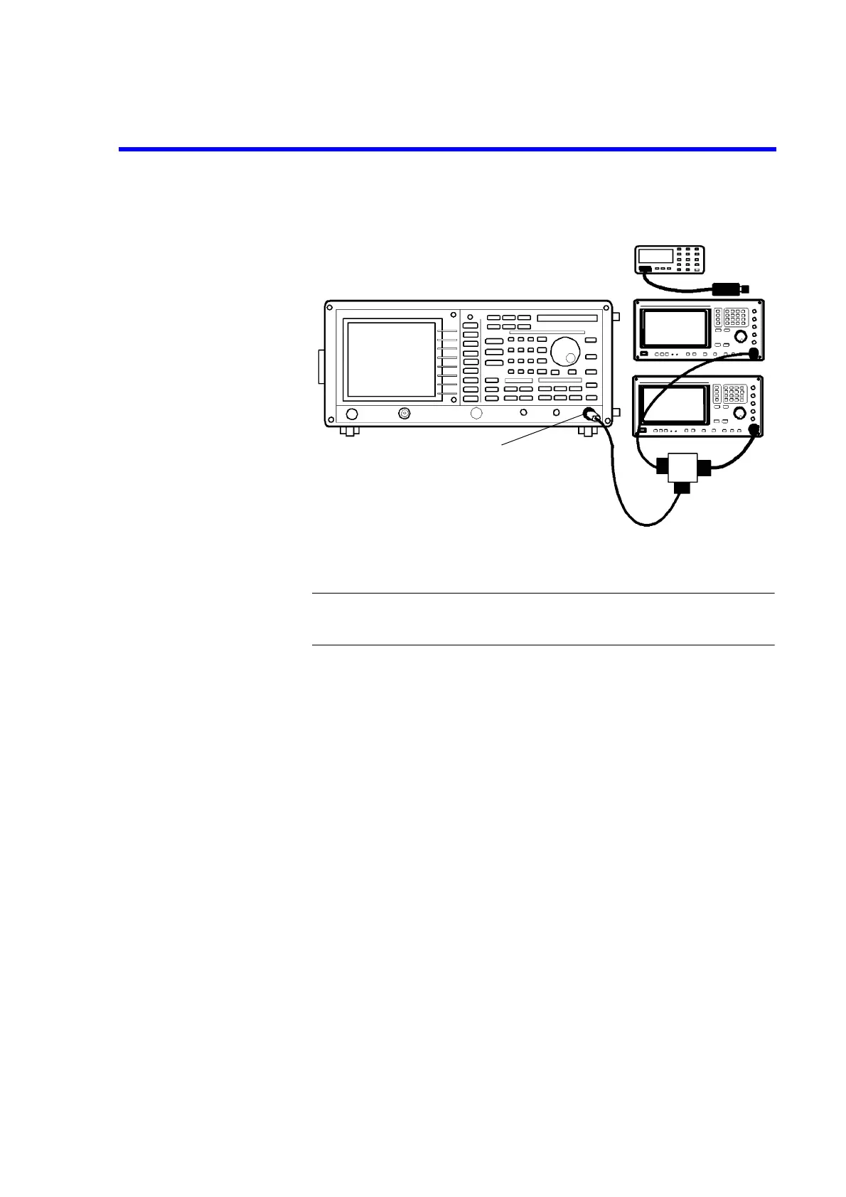
5. Connect the signal generators and power divider as shown Figure 5-18.
Figure 5-18 Setup of Third Order Intermodulation Distortion Test
CAUTION: Use only 75
Ω
ΩΩ
Ω
cables, connectors, or adapters on R3132N, or damage
to the input connector will occur.
6. On the both of signal generators, set controls as follows:
Signal Generator (SMP02)
Frequency: 200 MHz
Output Level: -10 dBm
RF Output: Off
Signal Generator (SMP04)
Frequency: 200.05 MHz
Output Level: -10 dBm
RF Output: Off
7. On the signal generator (SMP02), turn output level on.
8. On the signal generator (SMP02), adjust the output level so that power meter
reading is -10.0 dBm ±0.1 dB.
9. On the signal generator (SMP02), turn output level off.
10. On the signal generator (SMP04), turn output level on.
11. On the signal generator (SMP04), adjust the output level so that power meter
reading is -10.0 dBm ±0.1 dB.
12. On the signal generator (SMP04), turn output level off.
Minimum
Loss Pad (*1)
*1 R3132N only
 Loading...

