R3132 Series Spectrum Analyzer Operation Manual
2.2.2 Displaying Spectrums and Operating the Markers
2-20
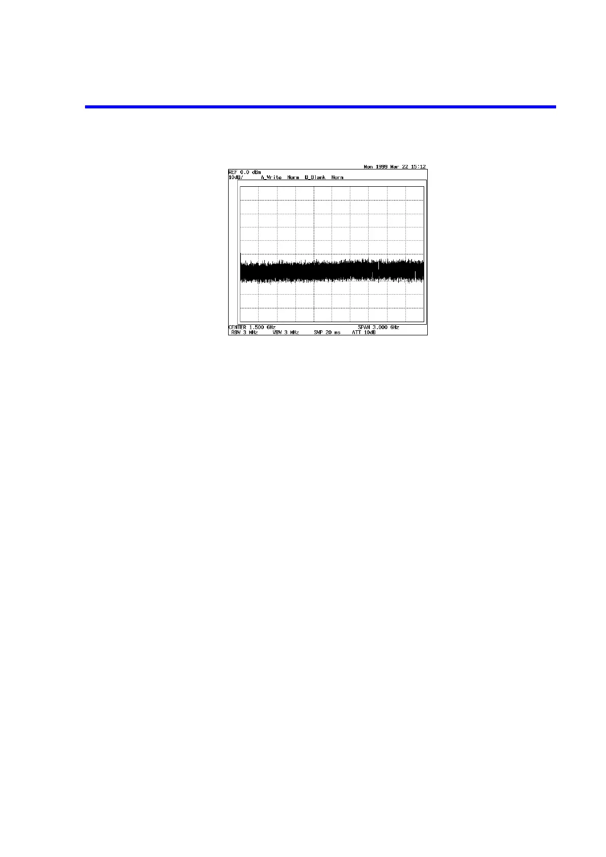
Figure 2-6 Factory Defaults Screen
Input signal connection
Connect the calibration signal used for the measurement.
7. Connect the N-BNC adapter to the INPUT connector on the front panel.
For the R3182, first connect the SMA-SMA adapter to the SMA-BNC adapter,
then connect this combined adapter to the INPUT connector on the front panel.
8. Connect the INPUT connector and the CAL OUT connector on the front panel
using the input cable provided as an accessory.
Setting the measurement conditions
This changes the analyzer settings so that the input signal is displayed more clearly.
 Loading...

