194 Installation, Operation, and Maintenance
A Cables and Connectors
G2916A/G2614A Trays
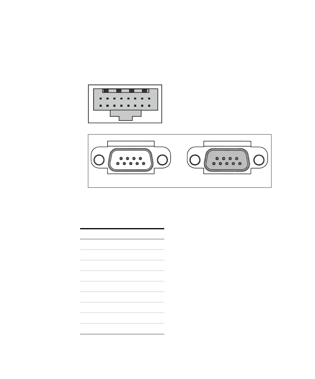
Figure 80 Tray connectors
Table 3 6 Tray connector P1, to GC or ALS controller
Pin Signal
A1 TXD
A2 RTS
A3 DTR
A4 MRESET
A5 GND
A6 VAC1
A7 GND
A8 VAC2
B1 RXD
P1, Back of tray, connection to GC or controller
Left side of tray
P9
J1
 Loading...