62 Installation, Operation, and Maintenance
Part 1, Installation
2 Installation
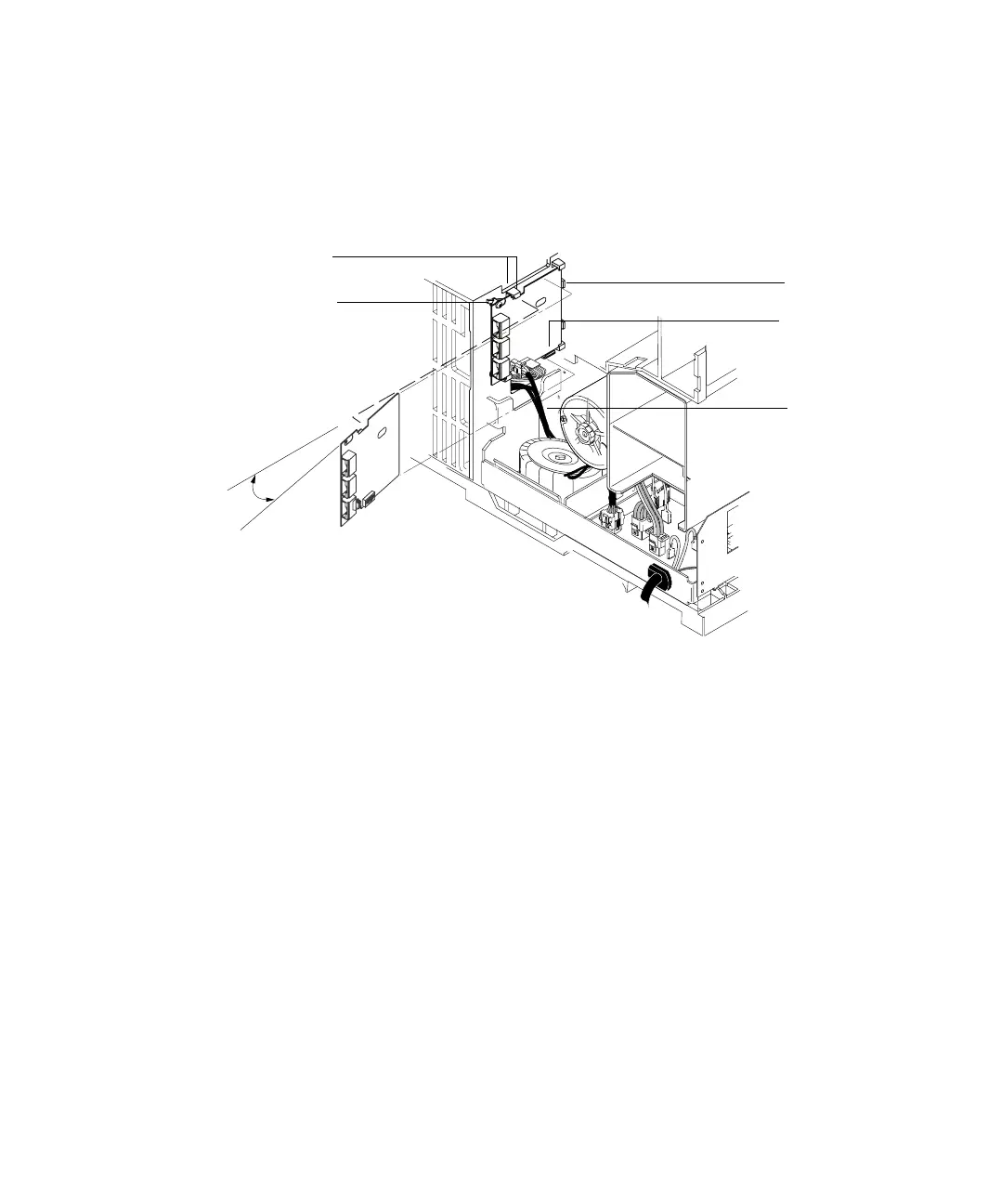
6 Secure the board to the chassis using two screws. The board should not be
stressed or bowed against the locking tab. See Figure 30.
7 Locate the 2-wire cable leading from the transformer and connect it to the
ALS Interface board at J5. See Figure 30 and Figure 31.
Figure 30 Installing the ALS interface board
Step 2.
Hold board
at an angle
Step 3.
Place board
in bracket
Step 4.
Align tabs
and cutouts
Step 5.
Insert board
to stops
Step 6.
Secure board
with screws
Step 7.
Connect
transformer
cable

 Loading...