A Accessories and platepads
(Bravo SRT only) Setting up an LT tip box location
172
Bravo Platform User Guide
(Bravo SRT only) Setting up an LT tip box location
About this topic
Read this topic if you have a Bravo SRT Platform and you are using the 250-µL tips. The
height limitation on the Bravo SRT requires a special platepad and a deck location
configured for the 250-µL tip box operations.
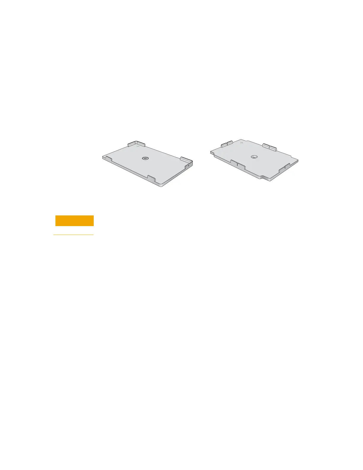
The following figure shows the SRT platepad options for tip operations.
Figure
SRT platepads: (A) ST tip loading station, and (B) SRT platepad for 250 µL LT tip boxes
Before you start
To prevent potential hardware crashes when using 250-µL tips, make sure you
understand the following limitations of the z-axis clearance on the Bravo SRT.
• Be aware that the Bravo SRT has insufficient clearance to move labware if the 250-
µL tips are installed on the liquid-handling head. The Bravo SRT can move labware
only if 250-µL tips are not on the liquid-handling head.
• Limit tips on and tips off tasks to deck locations where an SRT 250-µL tip box
platepad is physically installed and configured in the Bravo Diagnostics software.
This special platepad provides additional z-axis clearance, and is designed for a tip
box that holds 96 250-µL tips.
• Use labware classes for each deck location so that the 250-µL tip box operations
are not attempted at deck locations with insufficient z-axis clearance.
• Use VWorks Task Groups to ensure that tips on and tips off tasks are performed
before plate movement tasks in the protocol.
Ensure that you have the following:
• M5 hex wrench for removing a standard SRT platepad
• SRT platepad for 250-µL tip box
• Star-head screw and wrench for installing the SRT 250-µL tip box platepad