Chapter 1: Overview
44
The copper ports on the AT-x930-28GPX and AT-x930-52GPX Switches
have two LEDs that display link, activity and PoE information. The LEDs
are shown in Figure 9 on page 45.
Note
You can view the duplex mode information for the ports on the AT-
x930-28GPX and AT-x930-52GPX Switches with the management
software.
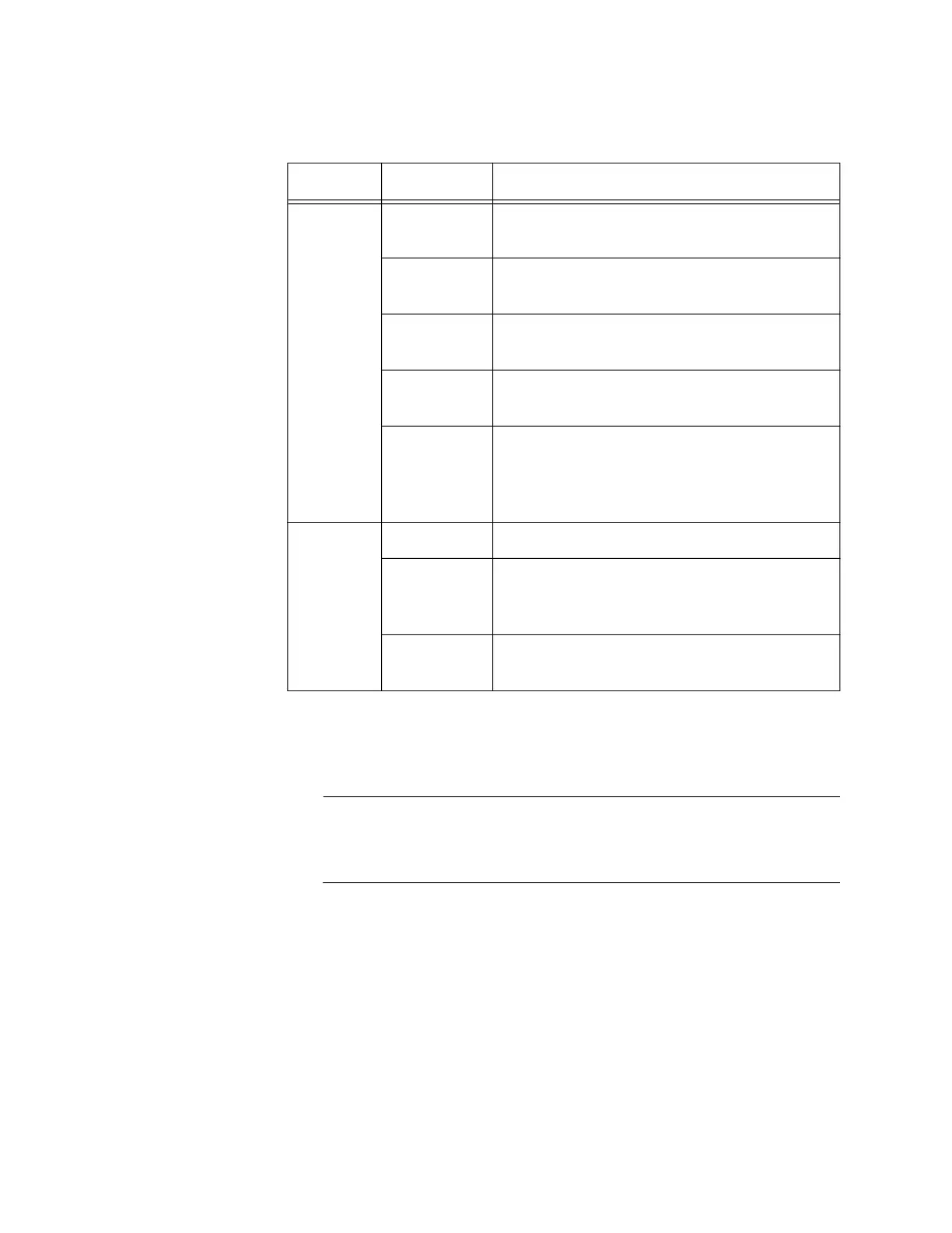
Table 7. LEDs on the 10/100/1000Base-T Ports on the AT-x930-28GTX,
AT-x930-28GSTX and AT-x930-52GTX Switches
LED State Description
Link/
Activity
LED
Solid Green A port has established a 1000 Mbps link to
a network device.
Flashing
Green
A port is transmitting or receiving data at
1000 Mbps.
Solid Amber A port has established a 10 or 100 Mbps
link to a network device.
Flashing
Amber
A port is transmitting or receiving data at 10
or 100 Mbps.
Off A port has not established a link with
another network device or the LEDs are
turned off. To turn on the LEDs, use the
eco-friendly button.
Duplex
Mode
LED
Green A port is operating in full duplex mode.
Amber A port is operating in half-duplex mode at 10
or 100 Mbps. (Half-duplex mode does not
apply to 1000 Mbps operation.)
Flashing
Amber
Collisions are occurring on a port operating
at 10 or 100 Mbps.
 Loading...


