Chapter 9: Wiring the DC Connector on the AT-PWR250-80 Power Supply
138
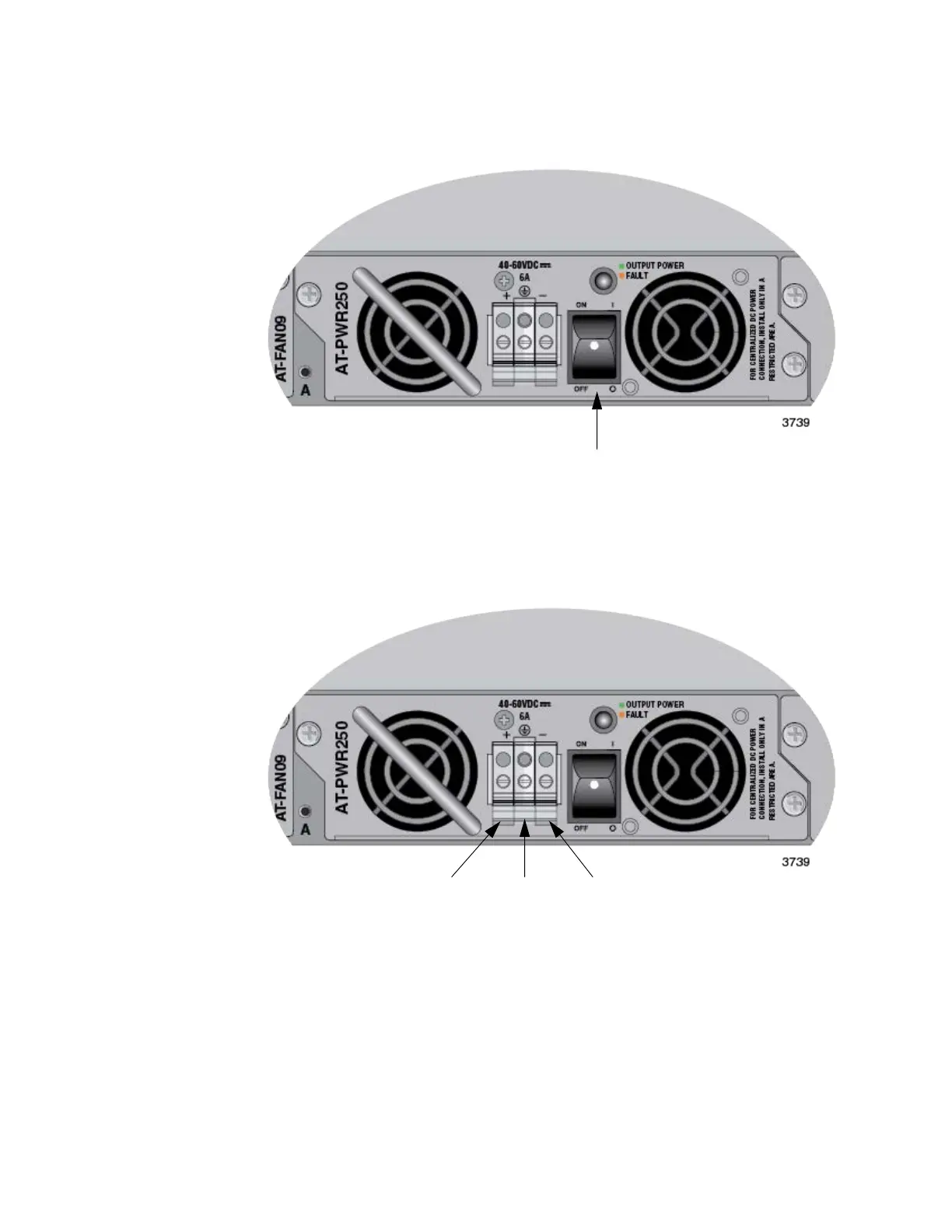
2. Verify that the On/Off switch on the power supply is in the Off position.
Refer to Figure 66 on page 138.
Figure 66. On/Off Switch on AT-PWR250-80 Power Supply
3. Use the legend above the terminal block to identify the terminals. The
terminals are positive, power supply ground and negative, from left
to right. Refer to Figure 67.
Figure 67. DC Terminal Block
4. With a 14-gauge wire-stripping tool, strip the three wires in the tray
cable coming from the DC input power source to 8mm 1mm (0.31 in.,
0.039 in.), as shown in Figure 68 on page 139.
On/Off Switch
+48 VDC Positive Ground -48 VDC Negative
TerminalTerminalTerminal
 Loading...


