x930 Series Installation Guide for Virtual Chassis Stacking
47
The possible states of the LEDs for the SFP ports are described in
Table 9.
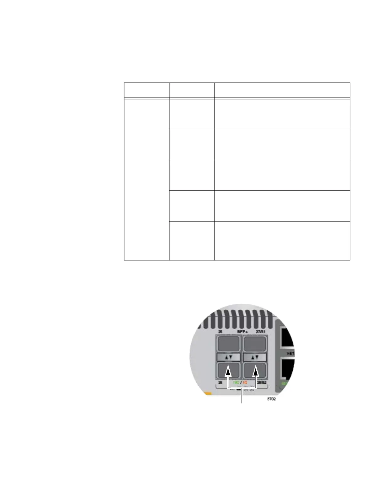
LEDs for the
SFP+ Ports
The LEDs for the SFP+ ports are located between the ports, as shown in
Figure 11. Each SFP+ port has one LED. The left LED is for the top port
and the right LED is for the bottom port.
Figure 11. SFP+ Port LEDs
Table 9. SFP Port LEDs on the AT-x930-28GSTX Switch
LED State Description
Link/Activity
Solid green The SFP transceiver in the port has
established a link at 1000 Mbps to a
network device.
Flashing
green
The SFP transceiver is receiving or
transmitting packets to a network device
at 1000 Mbps.
Solid amber The SFP transceiver in the port has
established a link at 100 Mbps to a
network device.
Flashing
amber
The SFP transceiver is receiving or
transmitting packets to a network device
at 100 Mbps.
Off The port is empty, the SFP transceiver
has not established a link to a network
device, or the LEDs are turned off. To turn
on the LEDs, use the eco-friendly button.
SFP Port LEDs
 Loading...


