EasyManuals Logo

Allied Telesis AlliedWare Plus Installation Guide

Allied Telesis AlliedWare Plus
214 pages
To Next Page IconTo Next Page
To Previous Page IconTo Previous Page
Page #90 background imageLoading...
Page #90 background image
Chapter 3: Beginning the Installation
90
Unpacking the Switch
Figure 31 lists the items in the accessory kit that comes with the switch. If
any item is missing or damaged, contact your Allied Telesis sales
representative for assistance.
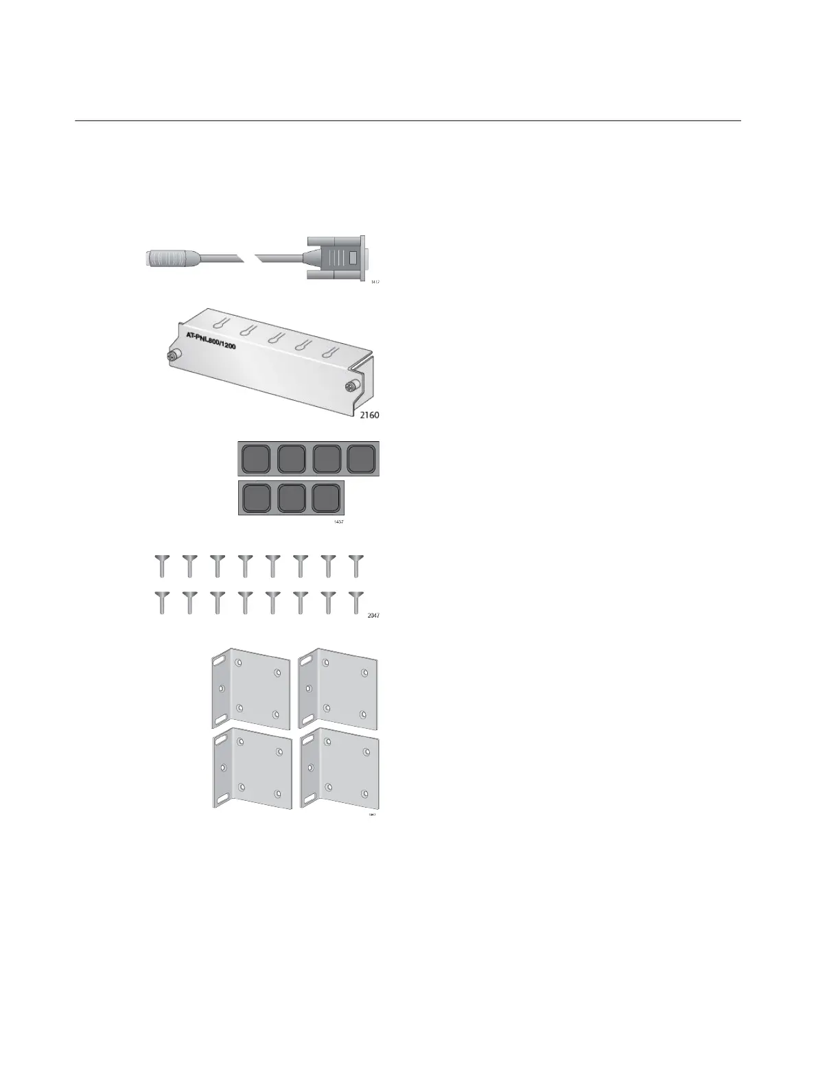
Figure 31. Accessory Kit
Four equipment rack or wall
mounting brackets
One 2 m (6.6 ft) local management
cable with RJ-45 (8P8C) and DB-9 (D-
sub 9-pin) connectors.
Sixteen bracket screws
Seven bumper feet
One AT-PNL800/1200 blank
panel

Table of Contents

Other manuals for Allied Telesis AlliedWare Plus

Questions and Answers:

Question and Answer IconNeed help?

Do you have a question about the Allied Telesis AlliedWare Plus and is the answer not in the manual?

Allied Telesis AlliedWare Plus Specifications

General IconGeneral
BrandAllied Telesis
ModelAlliedWare Plus
CategorySwitch
LanguageEnglish

Related product manuals