Chapter 1: Overview
56
You can install only one AT-x9EM/XT4 Card in the switch. It replaces the
AT-FAN09ADP Module in the back panel. The installation instructions are
provided in Chapter 5, “Installing AT-StackQS and AT-x9EM/XT4 Cards”
on page 103.
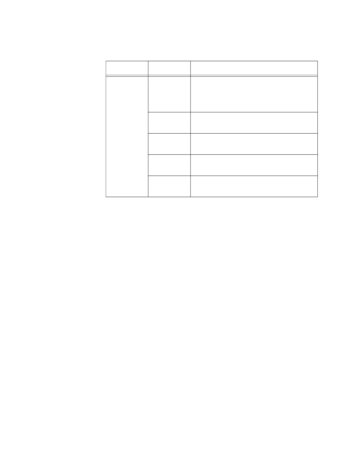
Table 15. AT-x9EM/XT4 Card LEDs
LED State Description
L/A (Link/
Activity)
Off The port is not connected to another
network device, the device is not powered
on, or the LEDs are turned off. To turn on
the LEDs, use the eco-friendly button.
Solid green The port has established a 10Gbps link to
a network device.
Flashing
green
The port is transmitting or receiving
network traffic at 10Gbps.
Solid amber The port has established a 1Gbps link to a
network device.
Flashing
amber
The port is transmitting or receiving
network traffic at 1Gbps.
 Loading...


