Appendix A: Technical Specifications
210
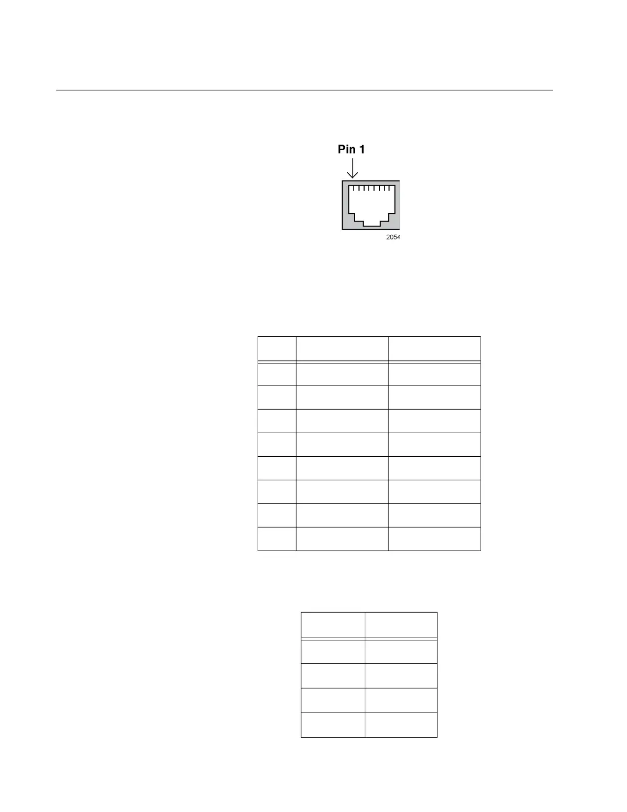
RJ-45 Copper Port Pinouts
Figure 93 illustrates the pin layout of the RJ-45 connectors and ports.
Figure 93. RJ-45 Socket Pin Layout (Front View)
Table 35 lists the pin signals for 10 and 100 Mbps.
Table 36 lists the pin signals when a port operating at 1000 Mbps.
Table 35. Pin Signals for 10 and 100 Mbps
Pin MDI Signal MDI-X Signal
1 TX+ RX+
2 TX- RX-
3 RX+ TX+
4 Not used Not used
5 Not used Not used
6 RX- TX-
7 Not used Not used
8 Not used Not used
Table 36. Pin Signals for 1000 Mbps
Pinout Pair
1 Pair 1 +
2 Pair 1 -
3 Pair 2 +
4 Pair 3 +
 Loading...


