Chapter 1: Overview
50
The states of the LED when the switch is not operating in the low power
mode are shown in Figure 13.
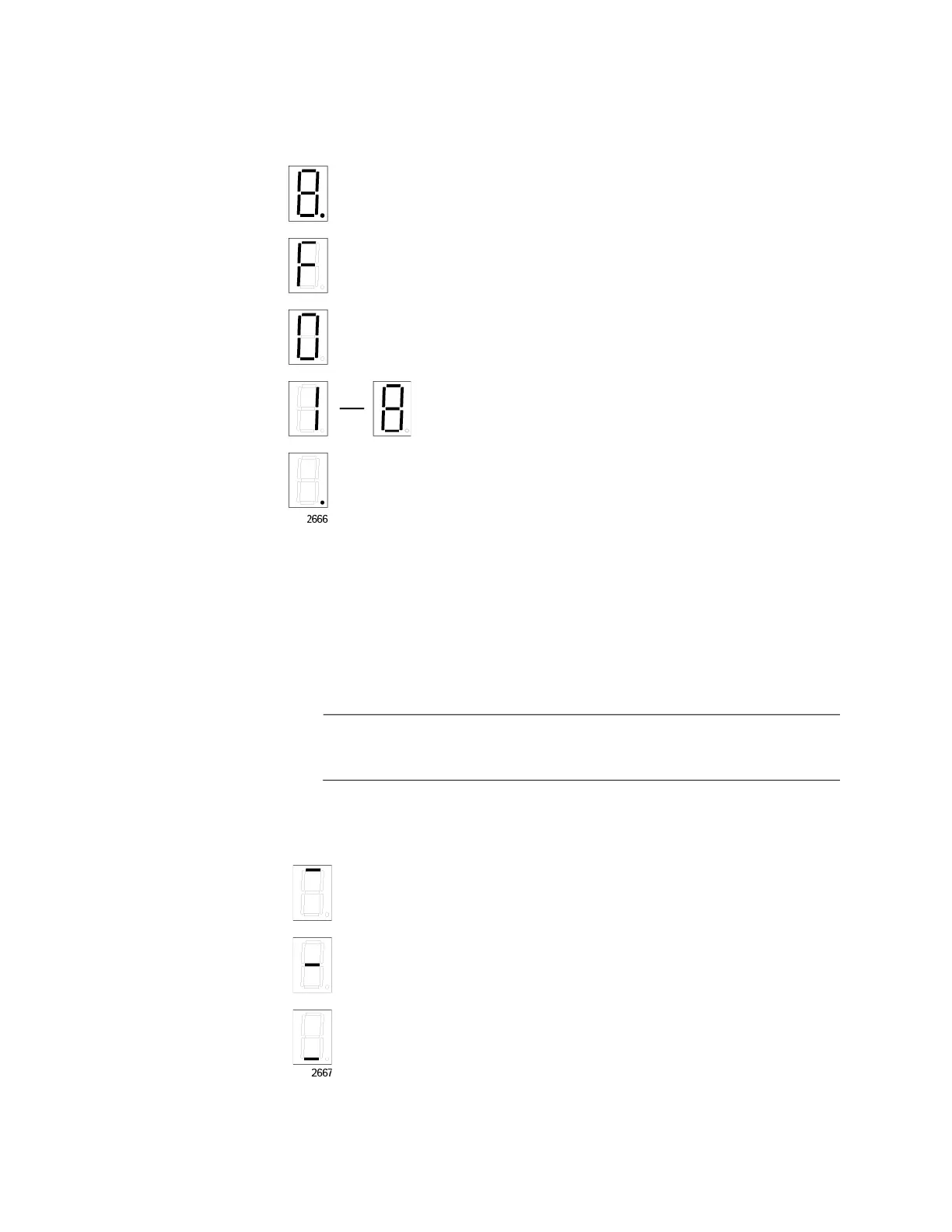
Figure 13. Switch ID LED
The switch displays the letter “F” for fault on the ID LED if it detects one of
the following problems:
A cooling fan has failed.
The internal temperature of the switch has exceeded the normal
operating range and the switch may shut down.
Note
You can use the SHOW SYSTEM ENVIRONMENT command in the
command line interface to identify the source of the problem.
The states of the LED when the switch is operating in the low power mode
are shown in Figure 14.
Figure 14. Switch ID LEDs in the Low Power Mode
The switch is booting up.
The switch has encountered a fault condition.
The switch is operating as a stand-alone unit, with the ID
number 0.
The switch has an ID number of 1 to 8 as part of a VCStack.
The dot in the lower right corner flashes when the switch
accesses USB memory.
The switch is the master switch of a VCStack.
The switch is operating as a stand-alone unit.
The switch is a member switch of a V
CStack.
 Loading...


