134
ML-5120A
2. Preparations for Operations
2. Preparations for Operations
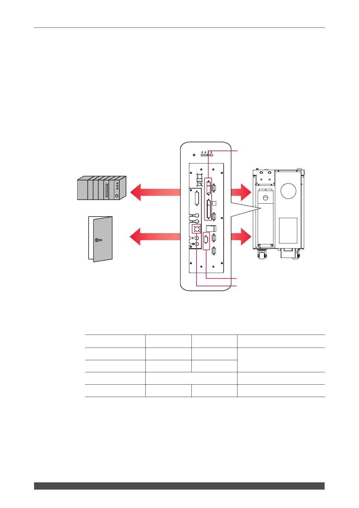
This section explains the devices and connectors required for laser processing
by external input/output signals (EXTERNAL CONTROL).
Connect the PLC to the EXT. I/O (1) or (2) connectors provided at the rear of the
main unit to control the main unit by executing the program from the outside.
Also, for preventing hazards, a remote interlock must be connected as a matter of
duty. The E-STOP connector (the REM. I/L connector when replacing our old prod-
ucts) is connected to the interlock of the door of the chamber or room for laser pro-
cessing. If the door is suddenly opened, the safety shutter is closed to cut o the
power supply of the ber laser module.
The plug, socket and case models of connectors are as follows.
Connector Plug / Socket Case Manufacturer
EXT. I/O (1) HDBB-25P(05) HDB-CTH(10)
HIROSE ELECTRIC CO., LTD.
EXT. I/O (2) HDCB-37P(05) HDC-CTH(10)
REM. I/L 116-12A10-2AF10.5 TAJIMI ELECTRONICS CO., LTD.
E-STOP HDBB-25S(05) HDB-CTH(10) HIROSE ELECTRIC CO., LTD.
⇒
Prepare a program and its development environment for laser control on the cus-
tomer side.
⇒
It is recommended to use the shielded cable for inputting and outputting the con-
trol signal.
⇒
To exhibit the shield eect, it is recommended to connect the shield of a cable to
the shield of a connector case or FG (ame ground), but it may be better not to
connect to a ground in some cases. Perform evaluation and connection to match
the operation of the overall system.
Rear of the main unit
EXT. I/O (1) D-Sub 25pin Connector
EXT. I/O (2) D-Sub 37pin Connector
Control signal input/output
Control signal input/output
PLC, etc.
Door interlock, etc.
REM. I/L Connector
E-STOP D-Sub 25pin Connector
 Loading...