2. Name and Function of Each Section on the Top Side
35
ML-5120A
Introduction Part
Installation and
Preparation Part
Operating Part Maintenance Part Appendixes
2. Name and Function of Each Section on the Top Side
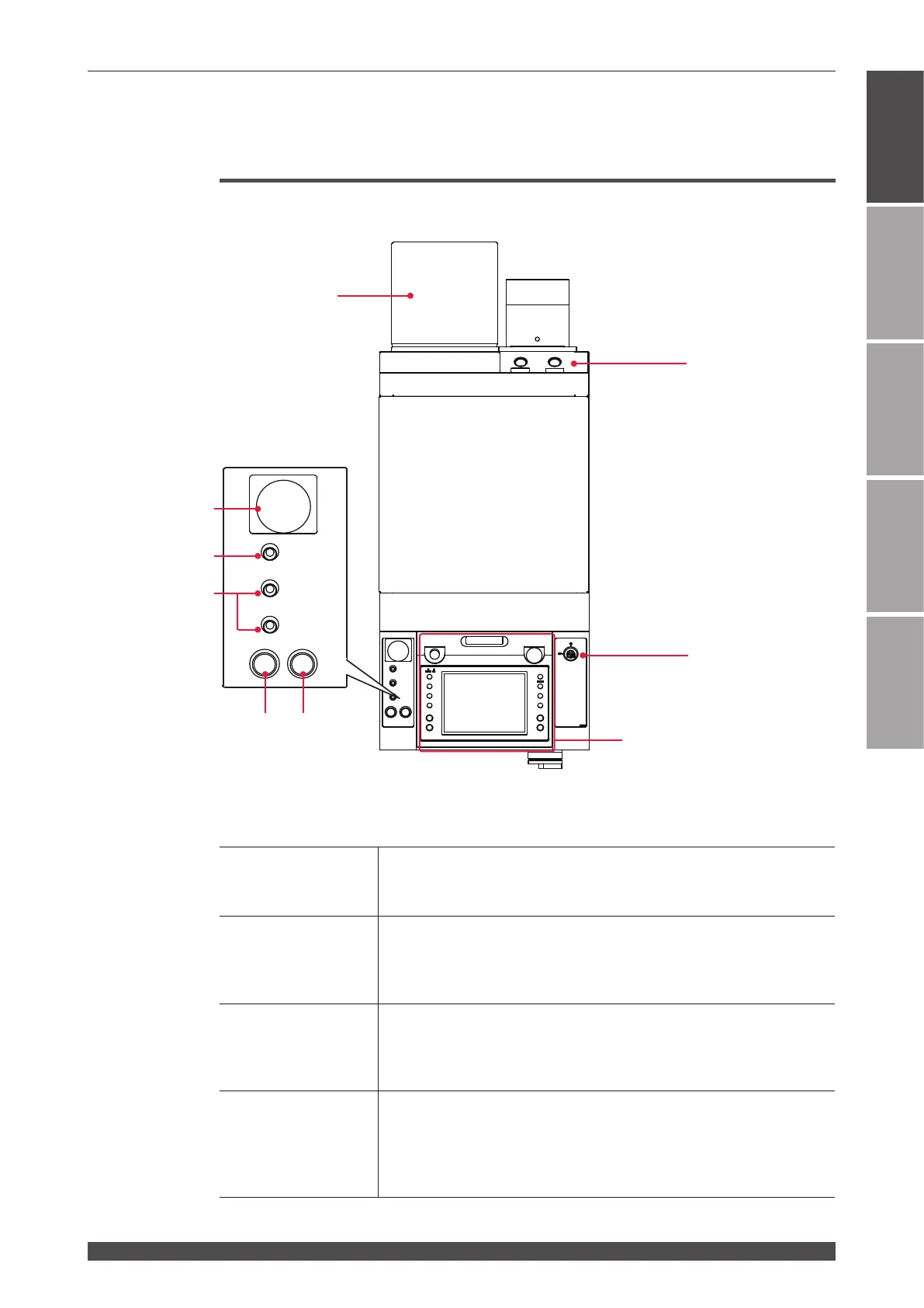
Top Cover Section
This section explains each section of the top cover of the main unit.
Function of Each Section on the Top Cover
(1) Optical Fiber In-
lets
Pass the optical bers through these holes.
The output units connected to the optical fiber input ports are num-
bered as 1 and 2, from the left.
(2) CONTROL Key-
switch
When the CONTROL keyswitch is turned ON with the MAIN POWER
switch ON, this keyswitch is operable. When the laser is not used, turn
OFF the CONTROL keyswitch and then pull out the key. The laser
safety supervisor should take charge of the keyswitch.
(3) Laser Controller
This controller sets processing conditions and operates the laser
equipment.
Setting items and set values are displayed on the touch panel type liquid
crystal display.
(4) EMERGENCY
STOP Button
This is an emergency stop button. With this button pressed, the laser
equipment operation is stopped and the same state as that provided by
turning OFF the CONTROL keyswitch is provided. When the pressed
button is turned in the direction of RESET (clockwise), the button is re-
set to the initial state.
Chapter 2 Name and Functions of Each Section
FIBER.OUT 1
FIBER.OUT 2
POWER
SHUTTER1
SHUTTER2
READY
LASER
(7)
(4)
(2)
(6)
(8)
(5)
(3)
(1)
1
2
(9)
 Loading...