10
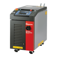
ML-5120A
Precautions for Handling
Precautions for Handling
Laser Safety Supervisor
⇒
Appoint a safety supervisor for all laser work.
The appointed safety supervisor must have sucient knowledge and experience
regarding both lasers and laser work.
⇒
The supervisor must control the keyswitch of the Laser, and must be responsible
for instructing operators in safety aspects of the Laser as well as directing the
laser work.
⇒
Establish and control a laser operation area.
The responsible person must isolate the laser operation area from other areas
and control it by fences and display signs indicating that the area is o-limits to
unauthorized personnel.
Routine Handling
⇒
Perform inspection periodically referring to the Maintenance Part, Chapter 1 "1.
Maintenance Parts and Standard Intervals of Inspection/Replacement" on page
179.
⇒
If the outside of the Laser is stained, wipe it with a dry cloth or a moistened cloth.
If it is badly stained, use neutral detergent or alcohol to clean it. Do not use paint
thinner, benzine, etc. which can discolor or deform the parts.
⇒
Do not put screws, coins, etc. in the Laser, since they can cause a malfunction.
⇒
Operate the switches and buttons carefully by hand. If they are operated roughly
or with the tip of a screwdriver, a pen, etc. they may be broken.
⇒
Operate the switches and buttons one at a time. If two or more of them are oper-
ated at a time, the Laser may have trouble or may be broken.
⇒
To restart the Laser, ensure that the Laser stops before turning ON the MAIN
POWER switch.
⇒
The outer panels and the covers are electrically connected to the main unit by
connecting cables. When the panels, covers and connecting cables are removed
and installed again, make sure that all these components are put back into place
correctly. Also, make sure that the cables do not block the optical path or get
caught between the outer panel and the frame.
⇒
To prevent damage, do not bend the optical ber beyond its minimum bending
radius or apply any forms of shock to it. For the ber’s minimum bending radius,
see the table below.
Minimum bending radius of the optical ber
Core Diameter Minimum Bending Radius
φ 0.2, 0.3, 0.4 mm 100 mm
φ 0.6 mm 150 mm
⇒
When outputting laser light, conrm that the optical ber(s) based on the num-
ber of deliveries is/are connected. Laser light cannot be output with the optical
ber(s) disconnected.
⇒
The life of the safety shutter is shortened if it is opened and closed at each laser
emission. It is recommended to minimize the use of the safety shutter such as
at startup of the equipment. The replacement of the safety shutter is done in our

 Loading...