3. Operating Procedure
127
ML-5120A
Chapter 3 Laser Processing by Laser Controller (PANEL CONTROL)
Introduction Part
Installation and
Preparation Part
Operating Part Maintenance Part Appendixes
3. Operating Procedure
This section explains the operating procedure for laser processing to be con-
trolled from the laser controller.
⇒
For the details of processing schedule settings, refer to Chapter 2, "4. Setting
the Laser Light Output Schedule" on page 89. For connector functions, refer to
Chapter 4, "3. Connector Functions" on page 135.
⇒
Before turning on the power supply, put pin No.25 (control switching) of the EXT.
I/O (1) connector to an open circuit to invalidate external input signals. As a re-
sult, the control by external input signals (EXTERNAL CONTROL) is invalidated
and "PANEL CONTROL" is displayed in "CONTROL DEVICE" on the STATUS
screen.
1
Starting the Laser
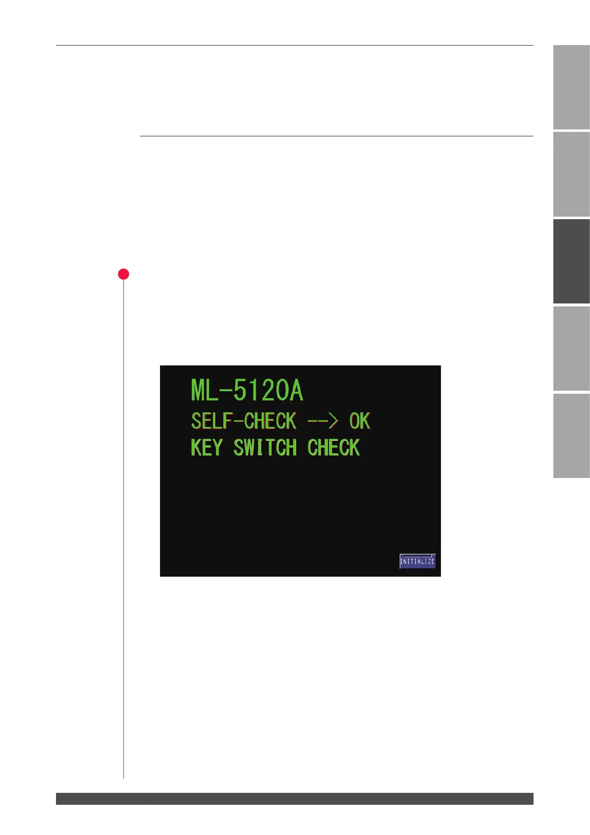
(1) Turn ON the MAIN POWER switch at the front of the main unit.
The power supply is turned ON and the POWER lamp comes on.
The safety shutter, memory, and power supply unit are automatically checked.
When no error is found, the KEY SWITCH CHECK screen is displayed.
 Loading...