38
ML-5120A
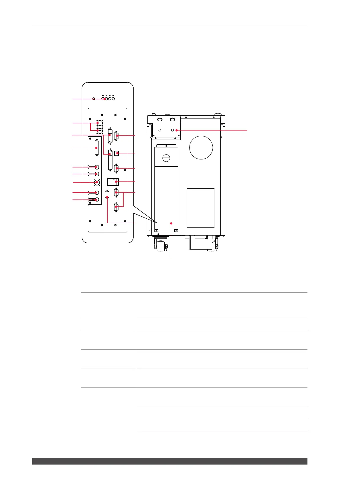
3. Name and Function of Each Section on the Rear Side
3. Name and Function of Each Section on the Rear Side
This section explains each section on the rear side.
Function of Each Section on the Rear Side
(1) Optical Fiber
Inlets
Pass the optical bers through these holes.
The output units connected to the optical ber input ports are numbered
as 1 and 2, from the right.
(2) Connector Cover
For the external I/O connectors.
(3) Power Supply
Terminals
Connect the terminals to a single-phase power supply of 200/220/240 V
AC, and the grounding conductor.
(4) RS-485 (1), (2)
Connectors
Connects a personal computer to use the external communication function.
(5) EXT. I/O (1), (2)
Connectors
Used to output signals, e.g., alarm signals and monitor judgment signals;
and to input signals, e.g., start signal and schedule signals.
(6) E-STOP Con-
nector
Used to connect to the Remote Interlock for emergency stop or input/
output Emergency signals.
(7) TH1 Connector
Connects the cable for the heat detector (option).
(8) TH2 Connector
Not used.
(With the connectror cover removed)
2
1
(1)
(9)
(4)
(11)
(3)
(2)
(6)
(5)
(14)
(15)
(13)
(12)
(16)
(10)
(17)
(8)
(7)
 Loading...